Chapter 3
57
Removing the Switch Cover
CAUTION:
Using metal tools to remove the Switch Cover may cause damage to the outer casing. The use of
plastic tools or fingers is recommended to remove the Switch Cover.
1.
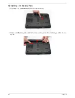
See “Removing the Battery Pack” on page 46.
2.
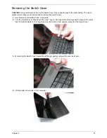
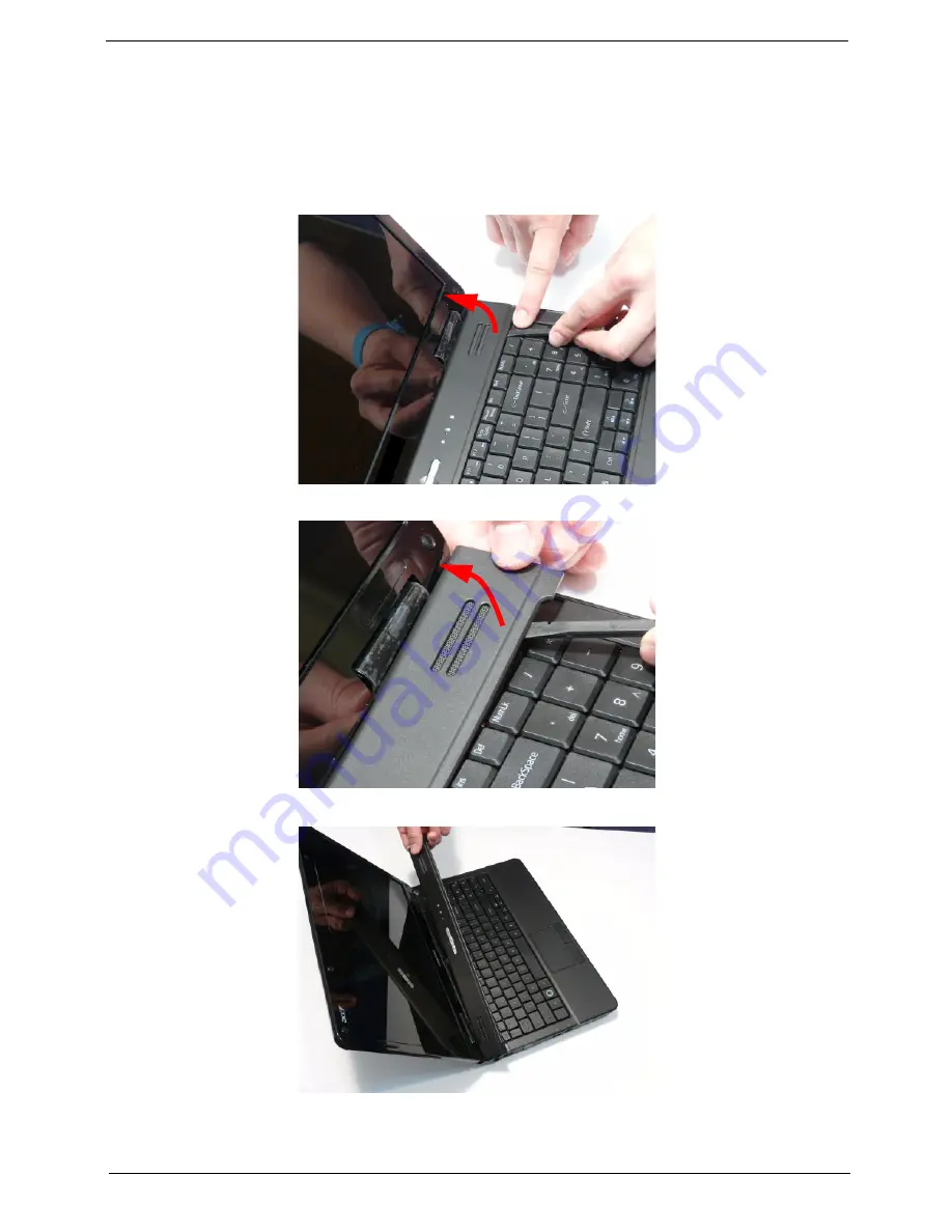
Turn the computer over. Press down the / and * keys on the right side of the Keyboard to expose the cutout.
Insert a suitable plastic tool (or finger) and pry the Switch Cover upward, away from the Upper Cover.
3.
Work along the Switch Cover toward the left hinge, gently prying up the cover as shown.
4.
Lift the Switch Cover clear of the computer.
Summary of Contents for Aspire 7715Z Series
Page 6: ...VI ...
Page 10: ...X Table of Contents ...
Page 13: ...Chapter 1 3 System Block Diagram ...
Page 30: ...20 Chapter 1 ...
Page 52: ...42 Chapter 2 ...
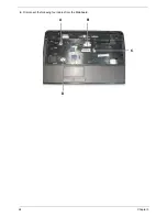
Page 74: ...64 Chapter 3 4 Disconnect the following four cables from the Mainboard A B C D ...
Page 87: ...Chapter 3 77 4 Using both hands lift the Thermal Module clear of the Mainboard ...
Page 89: ...Chapter 3 79 4 Lift the CPU Fan clear of the Mainboard as shown ...
Page 95: ...Chapter 3 85 5 Lift the LCD Panel clear of the module ...
Page 103: ...Chapter 3 93 9 The Antennas and cables appear as shown when correctly installed ...
Page 108: ...98 Chapter 3 2 Replace the four screws and screw caps provided ...
Page 113: ...Chapter 3 103 5 Replace the FFC and press down as indicated to secure it to the Upper Cover ...
Page 124: ...114 Chapter 3 17 Replace the two screws securing the LCD Module to the Lower Cover ...
Page 132: ...122 Chapter 3 ...
Page 164: ...154 Chapter 6 Rear Assembly No Description Acer P N 1 HDD Cover 2 3 RAM Cover 4 5 1 2 3 4 5 ...
Page 174: ...Appendix A 164 Model Definition and Configuration Appendix A ...
Page 196: ...186 Appendix C ...
Page 200: ...190 ...

