112
Chapter 3
Replacing the Thermal Module
IMPORTANT:
Apply a suitable thermal grease and ensure all heat pads are in place before replacing the Thermal
Module.
The following thermal grease types are approved for use:
•
Silmore GP50
•
Honeywell
•
Jet Motor 7762
The following thermal pads are approved for use:
•
Eapus XR-PE
1.
See “Replacing the CPU” on page 110.
2.
Remove all traces of thermal grease from the CPU using a lint-free cloth or cotton swab and Isopropyl
Alcohol, Acetone, or other approved cleaning agent.
3.
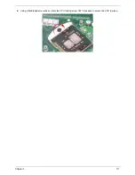
Apply a small amount of thermal grease to the centre of the CPU—there is no need to spread the grease
manually, the force used during the installation of the Thermal Module is sufficient.
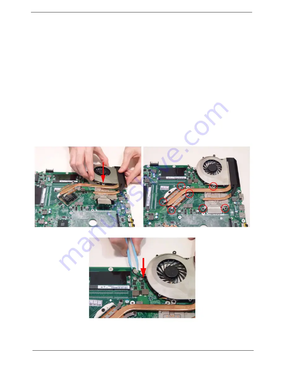
4.
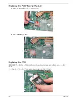
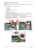
Align the screw holes on the Thermal Module and
Mainboard then replace the module. Keep the
module as level as possible to spread the thermal
grease evenly.
5.
Replace the seven (7) securing screws to secure
the Thermal Module in place.
6.
Connect the fan cable.
Summary of Contents for ASPIRE 7745
Page 6: ...VI ...
Page 10: ...X Table of Contents ...
Page 40: ...30 Chapter 1 ...
Page 56: ...46 Chapter 2 ...
Page 68: ...58 Chapter 3 5 Pull the WLAN module out and away ...
Page 73: ...Chapter 3 63 5 Remove the ODD bracket 6 Pry the ODD bezel off of the ODD module ...
Page 83: ...Chapter 3 73 5 Detach the Bluetooth module cable from the module ...
Page 91: ...Chapter 3 81 4 Lift the thermal module away from the main board ...
Page 96: ...86 Chapter 3 4 Unlock and disconnect the switch board FFC ...
Page 101: ...Chapter 3 91 4 Remove the bezel from the LCD module ...
Page 108: ...98 Chapter 3 5 Pry the right antenna from the casing ...
Page 111: ...Chapter 3 101 3 Lay the cables around the module edge ...
Page 115: ...Chapter 3 105 10 Place the LVDS cable into cable guides ...
Page 118: ...108 Chapter 3 4 Replace the two 2 bezel screws ...
Page 129: ...Chapter 3 119 4 Connect the Bluetooth module cable to the main board ...
Page 136: ...126 Chapter 3 6 Connect and lock the Power board FFC ...
Page 143: ...Chapter 3 133 4 Grasp the tab and slide the HDD firmly into the docking connector ...
Page 145: ...Chapter 3 135 4 Push the ODD completely into the bay until flush with the lower cover ...
Page 148: ...138 Chapter 3 ...
Page 166: ...156 Chapter 4 ...
Page 288: ...278 Appendix B ...
Page 290: ...280 ...


