4
Chapter 1
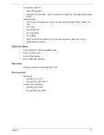
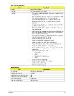
I/O Ports
•
Multi-in-1 card reader (SD
™
, MMC, MS, MS PRO, xD)
•
Four USB 2.0 ports
•
External display (VGA) port
•
HDMI
™
port with HDCP support
•
Headphone/speaker/line-out jack with S/PDIF support
•
Microphone-in jack
•
Ethernet (RJ-45) port
•
Modem (RJ-11) port
•
DC-in jack for AC adapter
Software
•
Productivity
•
Acer Backup Manager
•
Acer ePower Management
•
Acer eRecovery Management
•
Acer PowerSmart Manager
•
Adobe
®
Flash
®
Player 10
•
Adobe
®
Reader
®
9.1
•
eSobi
™
•
™
Setup
•
Google Toolbar
™
•
Microsoft
®
Office Personal 2007 (Service Pack 2) (Japan only, subject to customer request)
•
Microsoft
®
Office Trial (Service Pack 2)
•
Microsoft
®
Works SE 9 (Brazil, Canada, France, Germany, Poland, Russia, UK and US only)
•
Microsoft
®
Works 9
•
Microsoft
®
Works 8.5
•
Norton
™
Online Backup
•
Security
•
McAfee
®
Internet Security Suite 2009 Trial
•
McAfee
®
Virus Definitions
•
MyWinLocker
®
(except China, Hong Kong)
•
Multimedia
•
Acer Arcade
™
Deluxe
•
NTI Media Maker
™
•
Gaming
•
Oberon GameZone Acer Edition (except US, Canada, Hong Kong, Korea)
•
WildTangent
®
Acer Edition (US, Canada only)
Summary of Contents for ASPIRE 7745
Page 6: ...VI ...
Page 10: ...X Table of Contents ...
Page 40: ...30 Chapter 1 ...
Page 56: ...46 Chapter 2 ...
Page 68: ...58 Chapter 3 5 Pull the WLAN module out and away ...
Page 73: ...Chapter 3 63 5 Remove the ODD bracket 6 Pry the ODD bezel off of the ODD module ...
Page 83: ...Chapter 3 73 5 Detach the Bluetooth module cable from the module ...
Page 91: ...Chapter 3 81 4 Lift the thermal module away from the main board ...
Page 96: ...86 Chapter 3 4 Unlock and disconnect the switch board FFC ...
Page 101: ...Chapter 3 91 4 Remove the bezel from the LCD module ...
Page 108: ...98 Chapter 3 5 Pry the right antenna from the casing ...
Page 111: ...Chapter 3 101 3 Lay the cables around the module edge ...
Page 115: ...Chapter 3 105 10 Place the LVDS cable into cable guides ...
Page 118: ...108 Chapter 3 4 Replace the two 2 bezel screws ...
Page 129: ...Chapter 3 119 4 Connect the Bluetooth module cable to the main board ...
Page 136: ...126 Chapter 3 6 Connect and lock the Power board FFC ...
Page 143: ...Chapter 3 133 4 Grasp the tab and slide the HDD firmly into the docking connector ...
Page 145: ...Chapter 3 135 4 Push the ODD completely into the bay until flush with the lower cover ...
Page 148: ...138 Chapter 3 ...
Page 166: ...156 Chapter 4 ...
Page 288: ...278 Appendix B ...
Page 290: ...280 ...


