6
Chapter 1
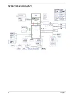
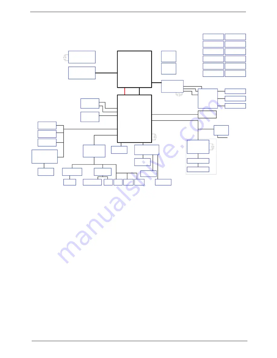
System Block Diagram
Azalia
ODD (SATA)
SATA1
X'TAL
14.318MHz
X'TAL
32.768KHz
PCI-Express
X4 DMI interface
Fan Driver
USB Port x 4
EC (WPC781)
USB 2.0
SELGO: SLG8SP595V
HDD (SATA) *2
SPI ROM
Touch Pad
USB 8
CCD
Giga-LAN
Atheros
X'TAL
25MHz
Transformer
USB 1, 3, 11, 12
SATA0
K/B COON.
CLOCK GENERATOR
SATA5
PCIE-6
AR8151
RJ45 Connector
800/ 1066 MHz
DDR III
Dual Channel
Main SPK
Line in
Audio CODEC
Int. D-MIC
Mini Card
USB10 & 13
PCIE-1 & 2
MIC Jack
SUBWOOFER
P19,20,21,22,23,24,25,26
PCIE
LVDS
CRT
SATA4
CHARGER
ISL88731
3/5V SYS PWR
ISL6237
CPU CORE PWR
ISL62882
DDR3 PWR
TPS5116
SO-DIMM 0
SO-DIMM 1
SO-DIMM 2
SO-DIMM 3
(PWM Type)
USB 10 & 13
WLAN / 2
USB 4
Bluetooth
Sub-Amplifier
(TPA3111 D1)
CardReader
Card Reader
Connector
HDMI
LVDS_CRT_HDMI
Switch Graphics
CRT
LVDS
HDMI
Gr
aphi
c
s
I
n
te
rf
ac
es
PCI-E
X16
D
D
R
S
Y
S
T
E
M
ME
MO
RY
FDI
PCI-E
SATA
HDA
RTC
P9
USB
DMI
FDI
SPI ROM
SPI
DMI
VTT 1.05V
UP61111 AQDD
intel
Clarksfield <Discrete only
w/4 DIMM>
Arrandale <UMA only>
Auburndale <UMA/SG>
rPGA 989
intel
Ibex Peak_M
<PCH>
INT_LVDS
800 MT/s 1066 MT/s
[Arrandale Only]
ALC669X
*
*
*
(Debug)
[Arrandale Only]
*
[Arrandale Only]
*
X'TAL
27.0MHz
CLKOUT_PEG_B
CLKOUT_PEG_1&3
CPU & PCH
XDP Conn.
4MB x1 (Basic ME+Braidwood)
CPU VTT
ARD: 1.05V
CFD: 1.1V
UP61111 AQDD
GPU CORE PWR
ISL6264
GPU IO PWR
ISL62827
DISCHARGER
THERMAL
PROTECTION
+1.0V/+1.5V
CPU VGFX_AXG
ISL62881
Lan/B
Alcor
AU6437
Winbond
Relteak
GMT G1453L
Rear Audio Amp
& Head phone
S/PDIF
PS8101
LS
Summary of Contents for ASPIRE 7745
Page 6: ...VI ...
Page 10: ...X Table of Contents ...
Page 40: ...30 Chapter 1 ...
Page 56: ...46 Chapter 2 ...
Page 68: ...58 Chapter 3 5 Pull the WLAN module out and away ...
Page 73: ...Chapter 3 63 5 Remove the ODD bracket 6 Pry the ODD bezel off of the ODD module ...
Page 83: ...Chapter 3 73 5 Detach the Bluetooth module cable from the module ...
Page 91: ...Chapter 3 81 4 Lift the thermal module away from the main board ...
Page 96: ...86 Chapter 3 4 Unlock and disconnect the switch board FFC ...
Page 101: ...Chapter 3 91 4 Remove the bezel from the LCD module ...
Page 108: ...98 Chapter 3 5 Pry the right antenna from the casing ...
Page 111: ...Chapter 3 101 3 Lay the cables around the module edge ...
Page 115: ...Chapter 3 105 10 Place the LVDS cable into cable guides ...
Page 118: ...108 Chapter 3 4 Replace the two 2 bezel screws ...
Page 129: ...Chapter 3 119 4 Connect the Bluetooth module cable to the main board ...
Page 136: ...126 Chapter 3 6 Connect and lock the Power board FFC ...
Page 143: ...Chapter 3 133 4 Grasp the tab and slide the HDD firmly into the docking connector ...
Page 145: ...Chapter 3 135 4 Push the ODD completely into the bay until flush with the lower cover ...
Page 148: ...138 Chapter 3 ...
Page 166: ...156 Chapter 4 ...
Page 288: ...278 Appendix B ...
Page 290: ...280 ...


