Chapter 4
151
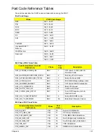
Post Code Reference Tables
These tables describe the POST codes and descriptions during the POST.
Post Code Range
SEC Phase POST Code Table
PEI Phase POST Code Table:
Phase
POST Code Range
SEC
0x01 - 0x0F
PEI
0x70 - 0x9F
DXE
0x40 - 0x6F
BDS
0x10 - 0x3F
SMM
0xA0 - 0xBF
S3
0xC0 - 0xCF
ASL
0x51 – 0x55
0xE1 – 0xE4
PostBDS
0xF9 – 0xFE
InsydeH2ODDT™
Reserve
0xD0 – 0xD7
OEM Reserve
0xE8 – 0xEB
Reserved
0xD8 – 0xE0
0xE5 – 0xE7
0xEC – 0xF8
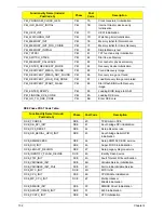
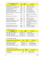
Functionality Name (Include\
PostCode.h)
Phase
Post
Code
Description
SEC_SYSTEM_POWER_ON
SEC
1
CPU power on and switch to
Protected mode
SEC_BEFORE_MICROCODE_PATCH
SEC
2
Patching CPU microcode
SEC_AFTER_MICROCODE_PATCH
SEC
3
Setup Cache as RAM
SEC_ACCESS_CSR
SEC
4
PCIE MMIO Base Address initial
SEC_GENERIC_MSRINIT
SEC
5
CPU Generic MSR initialization
SEC_CPU_SPEEDCFG
SEC
6
Setup CPU speed
SEC_SETUP_CAR_OK
SEC
7
Cache as RAM test
SEC_FORCE_MAX_RATIO
SEC
8
Tune CPU frequency ratio to
maximum level
SEC_GO_TO_SECSTARTUP
SEC
9
Setup BIOS ROM cache
SEC_GO_TO_PEICORE
SEC
0A
Enter Boot Firmware Volume
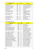
Functionality Name (Include\
PostCode.h)
Phase
Post
Code
Description
PEI_SIO_INIT
PEI
70
Super I/O Initialization
PEI_CPU_REG_INIT
PEI
71
CPU Early Initialization
PEI_PCIE_MMIO_INIT
PEI
74
PCIE MMIO BAR Initialization
PEI_NB_REG_INIT
PEI
75
North Bridge Early Initialization
PEI_SB_REG_INIT
PEI
76
South Bridge Early Initialization
PEI_TPM_INIT
PEI
78
TPM Initialization
PEI_SMBUS_INIT
PEI
79
SMBUS Early Initialization
Summary of Contents for ASPIRE 7745
Page 6: ...VI ...
Page 10: ...X Table of Contents ...
Page 40: ...30 Chapter 1 ...
Page 56: ...46 Chapter 2 ...
Page 68: ...58 Chapter 3 5 Pull the WLAN module out and away ...
Page 73: ...Chapter 3 63 5 Remove the ODD bracket 6 Pry the ODD bezel off of the ODD module ...
Page 83: ...Chapter 3 73 5 Detach the Bluetooth module cable from the module ...
Page 91: ...Chapter 3 81 4 Lift the thermal module away from the main board ...
Page 96: ...86 Chapter 3 4 Unlock and disconnect the switch board FFC ...
Page 101: ...Chapter 3 91 4 Remove the bezel from the LCD module ...
Page 108: ...98 Chapter 3 5 Pry the right antenna from the casing ...
Page 111: ...Chapter 3 101 3 Lay the cables around the module edge ...
Page 115: ...Chapter 3 105 10 Place the LVDS cable into cable guides ...
Page 118: ...108 Chapter 3 4 Replace the two 2 bezel screws ...
Page 129: ...Chapter 3 119 4 Connect the Bluetooth module cable to the main board ...
Page 136: ...126 Chapter 3 6 Connect and lock the Power board FFC ...
Page 143: ...Chapter 3 133 4 Grasp the tab and slide the HDD firmly into the docking connector ...
Page 145: ...Chapter 3 135 4 Push the ODD completely into the bay until flush with the lower cover ...
Page 148: ...138 Chapter 3 ...
Page 166: ...156 Chapter 4 ...
Page 288: ...278 Appendix B ...
Page 290: ...280 ...


