Chapter 1
15
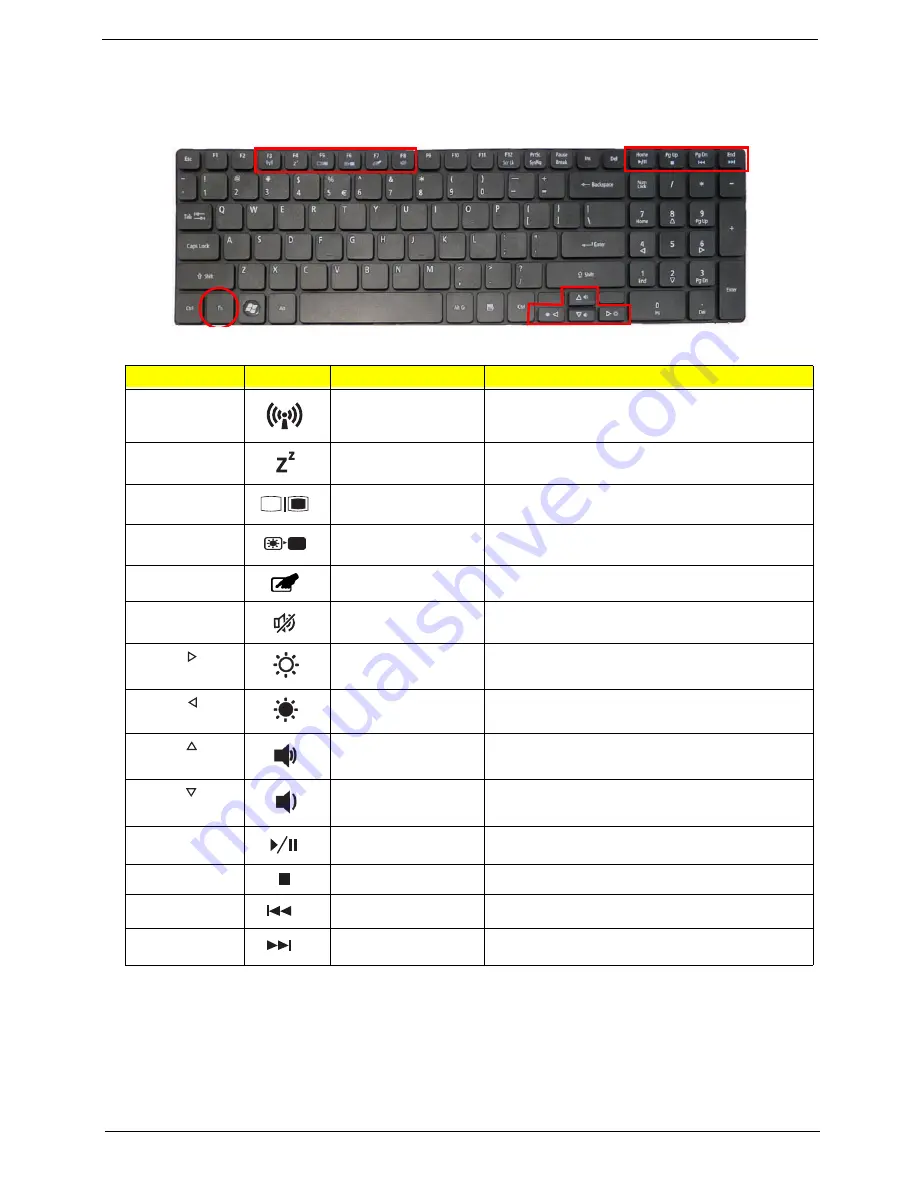
Hot Keys
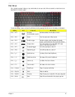
The computer employs hotkeys or key combinations to access most of the computer's controls like screen
brightness and volume output.
To activate hotkeys, press and hold the
<Fn>
key before pressing the other key in the hotkey combination.
Hotkey
Icon
Function
Description
<Fn> + <F3>
Wireless
communication switch
Enables/disables the Wireless function.
<Fn> + <F4>
Sleep
Puts the computer in Sleep mode.
<Fn> + <F5>
Display toggle
Switches display output between the display
screen, external monitor (if connected) and both.
<Fn> + <F6>
Screen blank
Turns the display screen backlight off to save
power. Press any key to return.
<Fn> + <F7>
Touchpad toggle
Turns the touchpad on and off.
<Fn> + <F8>
Speaker toggle
Turns the speakers on and off.
<Fn> + < >
Brightness up
Increases the screen brightness.
<Fn> + < >
Brightness down
Decreases the screen brightness.
<Fn> + < >
Volume up
Increases the sound volume.
<Fn> + < >
Volume down
Decreases the sound volume.
<Fn> + <Home>
Play/Pause
Plays or pauses media files
<Fn> + <Pg Up>
Stop
Stops media file
<Fn> + <Pg Dn>
Previous
Plays the previous media file in the play sequence
<Fn> + <End>
Next
Plays the next media file in the play sequence
Summary of Contents for ASPIRE 7745
Page 6: ...VI ...
Page 10: ...X Table of Contents ...
Page 40: ...30 Chapter 1 ...
Page 56: ...46 Chapter 2 ...
Page 68: ...58 Chapter 3 5 Pull the WLAN module out and away ...
Page 73: ...Chapter 3 63 5 Remove the ODD bracket 6 Pry the ODD bezel off of the ODD module ...
Page 83: ...Chapter 3 73 5 Detach the Bluetooth module cable from the module ...
Page 91: ...Chapter 3 81 4 Lift the thermal module away from the main board ...
Page 96: ...86 Chapter 3 4 Unlock and disconnect the switch board FFC ...
Page 101: ...Chapter 3 91 4 Remove the bezel from the LCD module ...
Page 108: ...98 Chapter 3 5 Pry the right antenna from the casing ...
Page 111: ...Chapter 3 101 3 Lay the cables around the module edge ...
Page 115: ...Chapter 3 105 10 Place the LVDS cable into cable guides ...
Page 118: ...108 Chapter 3 4 Replace the two 2 bezel screws ...
Page 129: ...Chapter 3 119 4 Connect the Bluetooth module cable to the main board ...
Page 136: ...126 Chapter 3 6 Connect and lock the Power board FFC ...
Page 143: ...Chapter 3 133 4 Grasp the tab and slide the HDD firmly into the docking connector ...
Page 145: ...Chapter 3 135 4 Push the ODD completely into the bay until flush with the lower cover ...
Page 148: ...138 Chapter 3 ...
Page 166: ...156 Chapter 4 ...
Page 288: ...278 Appendix B ...
Page 290: ...280 ...

