18
Chapter 1
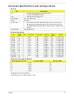
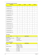
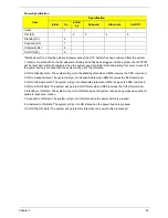
CPU Fan True Value Table (TJ90-CPU)
Throttling 50%: On= 87°C; OFF=84°C
OS shut down at 105°C; H/W shut down at 110°C
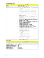
Power and Keyboard Controller
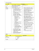
Media Card Reader
Camera 1.3M
CPU Temperature (Celsius)
Fan Speed (RPM)
SPL Spec (dBA)
45
2700
31
53
3000
34
65
3350
38
80
3650
40
86
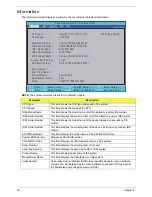
Item
Specification
Keyboard Controller
ACER AC7T_A10B AC7T Internal 17
Total number of keypads
103/104/107
Windows logo key
Yes
Hotkeys
Supports application keys for Windows 7 version
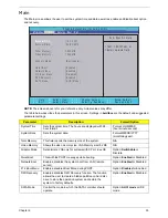
Item
Specification
Chipset
AU6437-GBL -GR
Package
LQFP
Features
•
Fully compatible with USB2.0 High Speed and backward
compatible with USB1.1 specifications
•
Supports multiple flash card interfaces, including SD/
MMC/xD/MS.
•
Supports single LUN
•
Supports both Windows and Mac OS
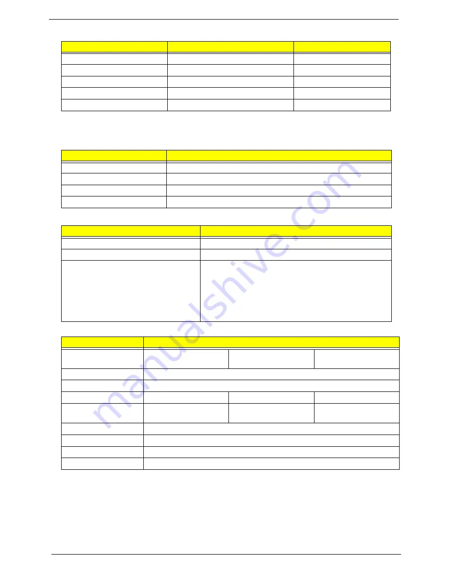
Item
Specifications
Vendor and model
SUYIN HF1315-S32B-
OV0
Chicony CNF9157
Liteon 09P2BF127 /
Liteon 09P2SF119
Type
CMOS image sensor with SXGA
Interface
USB Port 2.0
Focusing distance
70cm
70 cm
60 cm
Dimensions (L x W x H
mm)
65 x 8.0 x 3.74 mm
65.0±0.3 X 8.0±0.1 X
3.69+0.11/-0.2 mm
65.0 x 8.0 x 3.53 ±
0.2mm
Sensor type
OV9665
Pixel resolution
1280x1024
Pixel size
2 µm x 2 µm
Image size
3.89mm(H) X 2.43mm(V)
Summary of Contents for ASPIRE 7745
Page 6: ...VI ...
Page 10: ...X Table of Contents ...
Page 40: ...30 Chapter 1 ...
Page 56: ...46 Chapter 2 ...
Page 68: ...58 Chapter 3 5 Pull the WLAN module out and away ...
Page 73: ...Chapter 3 63 5 Remove the ODD bracket 6 Pry the ODD bezel off of the ODD module ...
Page 83: ...Chapter 3 73 5 Detach the Bluetooth module cable from the module ...
Page 91: ...Chapter 3 81 4 Lift the thermal module away from the main board ...
Page 96: ...86 Chapter 3 4 Unlock and disconnect the switch board FFC ...
Page 101: ...Chapter 3 91 4 Remove the bezel from the LCD module ...
Page 108: ...98 Chapter 3 5 Pry the right antenna from the casing ...
Page 111: ...Chapter 3 101 3 Lay the cables around the module edge ...
Page 115: ...Chapter 3 105 10 Place the LVDS cable into cable guides ...
Page 118: ...108 Chapter 3 4 Replace the two 2 bezel screws ...
Page 129: ...Chapter 3 119 4 Connect the Bluetooth module cable to the main board ...
Page 136: ...126 Chapter 3 6 Connect and lock the Power board FFC ...
Page 143: ...Chapter 3 133 4 Grasp the tab and slide the HDD firmly into the docking connector ...
Page 145: ...Chapter 3 135 4 Push the ODD completely into the bay until flush with the lower cover ...
Page 148: ...138 Chapter 3 ...
Page 166: ...156 Chapter 4 ...
Page 288: ...278 Appendix B ...
Page 290: ...280 ...

