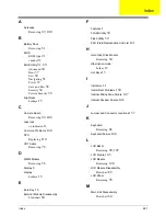
Index
281
A
Antennas
Removing
97, 100
B
Battery Pack
Removing
51
BIOS
ROM type
21
vendor
21
BIOS Utility
31–39
Advanced
34
Boot
37
Exit
38
Navigating
31
Power
37
Save and Exit
38
Security
34
System Security
38
brightness
hotkeys
15
C
Camera Board
Removing
92, 106
caps lock
on indicator
11
Common Problems
140
CPU
Replacing
110
CRT Cable
Removing
76
D
DIMM Module
Removing
56
Display
6
display
hotkeys
15
E
Euro Key
16
External Module Disassembly
Flowchart
50
F
Features
1
FLASH Utility
39
Flash Utility
39
FRU (Field Replaceable Unit) List
161
H
Hard Disk Drive Module
Removing
54
Hibernation mode
hotkey
15
Hot Keys
13
I
Indicators
11
Intermittent Problems
150
Internal Microphone Failure
147
Internal Speaker Failure
146
J
Jumper and Connector Locations
157
K
Keyboard
Removing
66
Keyboard Failure
144
L
LCD Bezel
Removing
90, 107
LCD Failure
143
LCD Module
Removing
120
LCD Module Disassembly
Flowchart
89
LCD Panel
Removing
93
M
Main Unit Disassembly
Flowchart
64
Index
Summary of Contents for ASPIRE 7745
Page 6: ...VI ...
Page 10: ...X Table of Contents ...
Page 40: ...30 Chapter 1 ...
Page 56: ...46 Chapter 2 ...
Page 68: ...58 Chapter 3 5 Pull the WLAN module out and away ...
Page 73: ...Chapter 3 63 5 Remove the ODD bracket 6 Pry the ODD bezel off of the ODD module ...
Page 83: ...Chapter 3 73 5 Detach the Bluetooth module cable from the module ...
Page 91: ...Chapter 3 81 4 Lift the thermal module away from the main board ...
Page 96: ...86 Chapter 3 4 Unlock and disconnect the switch board FFC ...
Page 101: ...Chapter 3 91 4 Remove the bezel from the LCD module ...
Page 108: ...98 Chapter 3 5 Pry the right antenna from the casing ...
Page 111: ...Chapter 3 101 3 Lay the cables around the module edge ...
Page 115: ...Chapter 3 105 10 Place the LVDS cable into cable guides ...
Page 118: ...108 Chapter 3 4 Replace the two 2 bezel screws ...
Page 129: ...Chapter 3 119 4 Connect the Bluetooth module cable to the main board ...
Page 136: ...126 Chapter 3 6 Connect and lock the Power board FFC ...
Page 143: ...Chapter 3 133 4 Grasp the tab and slide the HDD firmly into the docking connector ...
Page 145: ...Chapter 3 135 4 Push the ODD completely into the bay until flush with the lower cover ...
Page 148: ...138 Chapter 3 ...
Page 166: ...156 Chapter 4 ...
Page 288: ...278 Appendix B ...
Page 290: ...280 ...


