130
Chapter 4
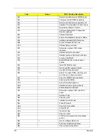
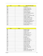
82h
Detect and install external RS232 ports
83h
Configure non-MCD IDE controllers
84h
Detect and install external parallel ports
85h
Initialize PC-compatible PnP ISA devices
86h
Re-initialize onboard I/O ports
87h
Configure Motherboard Configurable
Devices (optional)
88h
Initialize BIOS Area
89h
Enable Non-Maskable Interrupts (NMIs)
8Ah
Initialize Extended BIOS Data Area
8Bh
Test and initialize PS/2 mouse
8Ch
Initialize floppy controller
8Fh
Determine number of ATA drives
(optional)
90h
Initialize hard-disk controllers
91h
Initialize local-bus hard-disk controllers
92h
Jump to UserPatch2
93h
Build MPTABLE for multi-processor
boards
95h
Install CD ROM for boot
96h
Clear huge ES segment register
97h
Fixup Multi Processor table
98h
1-2
Search for option ROMs. One long, two
short beeps on checksum failure.
99h
Check for SMART drive (optional)
9Ah
Shadow option ROMs
9Ch
Set up Power Management
9Dh
Initialize security engine (optional)
9Eh
Enable hardware interrupts
9Fh
Determine number of ATA and SCSI
drives
A0h
Set time of day
A2h
Check key lock
A4h
Initialize Typematic rate
A8h
Erase F2 prompt
AAh
Scan for F2 key stroke
ACh
Enter SETUP
AEh
Clear Boot flag
B0h
Check for errors
B2h
POST done- prepare to boot operating
system
B4h
1
One short beep before boot
B5h
Terminate QuietBoot (optional)
B6h
Check password (optional)
Code
Beeps
POST Routine Description
Summary of Contents for Aspire 8530 Series
Page 6: ...VI ...
Page 10: ...X Table of Contents ...
Page 14: ...4 Chapter 1 System Block Diagram For Aspire 8730 8730Z Series ...
Page 15: ...Chapter 1 5 For Aspire 8530 Series ...
Page 46: ...36 Chapter 1 ...
Page 60: ...50 Chapter 2 ...
Page 77: ...Chapter 3 67 2 Remove the two captive screws securing the hard disk drive cover ...
Page 100: ...90 Chapter 3 19 Disconnect the Media console cable from LEDB1 on the main board ...
Page 118: ...108 Chapter 3 21 Remove the USB board module from the lower case ...
Page 124: ...114 Chapter 3 13 Detach any adhesive tapes and any cable that is glued to the LCD panel ...
Page 125: ...Chapter 3 115 14 Disconnect the FPC cable from the LCD panel ...
Page 142: ...132 Chapter 4 F5h Boot to Mini DOS F6h Clear Huge Segment F7h Boot to Full DOS Code Beeps ...
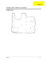
Page 149: ...Chapter 5 139 Motherboard Jumper and Connector Locations Chapter 5 ...
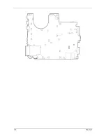
Page 150: ...140 Chapter 5 ...
Page 154: ...144 Chapter 5 ...
Page 156: ...146 Chapter 6 Aspire 8730 8730Z 8530 Series Exploded Diagram ...
Page 188: ...Appendix A 178 ...
Page 192: ...182 Appendix B ...
Page 194: ...184 Appendix C ...


