Chapter 4
131
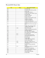
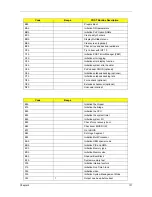
B9h
Prepare Boot
BAh
Initialize DMI parameters
BBh
Initialize PnP Option ROMs
BCh
Clear parity checkers
BDh
Display MultiBoot menu
BEh
Clear screen (optional)
BFh
Check virus and backup reminders
C0h
Try to boot with INT 19
C1h
Initialize POST Error Manager (PEM)
C2h
Initialize error logging
C3h
Initialize error display function
C4h
Initialize system error handler
C5h
PnPnd dual CMOS (optional)
C6h
Initialize notebook docking (optional)
C7h
Initialize notebook docking late
C8h
Force check (optional)
C9h
Extended checksum (optional)
D2h
Unknown interrupt
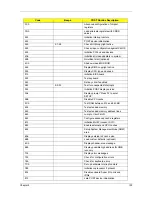
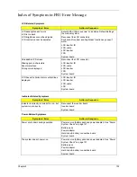
Code
Beeps
E0h
Initialize the chipset
E1h
Initialize the bridge
E2h
Initialize the CPU
E3h
Initialize the system timer
E4h
Initialize system I/O
E5h
Check force recovery boot
E6h
Checksum BIOS ROM
E7h
Go to BIOS
E8h
Set Huge Segment
E9h
Initialize Multi Processor
EAh
Initialize OEM special code
EBh
Initialize PIC and DMA
ECh
Initialize Memory type
EDh
Initialize Memory size
EEh
Shadow Boot Block
EFh
System memory test
F0h
Initialize interrupt vectors
F1h
Initialize Run Time Clock
F2h
Initialize video
F3h
Initialize System Management Mode
F4h
1
Output one beep before boot
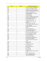
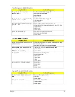
Code
Beeps
POST Routine Description
Summary of Contents for Aspire 8530 Series
Page 6: ...VI ...
Page 10: ...X Table of Contents ...
Page 14: ...4 Chapter 1 System Block Diagram For Aspire 8730 8730Z Series ...
Page 15: ...Chapter 1 5 For Aspire 8530 Series ...
Page 46: ...36 Chapter 1 ...
Page 60: ...50 Chapter 2 ...
Page 77: ...Chapter 3 67 2 Remove the two captive screws securing the hard disk drive cover ...
Page 100: ...90 Chapter 3 19 Disconnect the Media console cable from LEDB1 on the main board ...
Page 118: ...108 Chapter 3 21 Remove the USB board module from the lower case ...
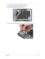
Page 124: ...114 Chapter 3 13 Detach any adhesive tapes and any cable that is glued to the LCD panel ...
Page 125: ...Chapter 3 115 14 Disconnect the FPC cable from the LCD panel ...
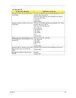
Page 142: ...132 Chapter 4 F5h Boot to Mini DOS F6h Clear Huge Segment F7h Boot to Full DOS Code Beeps ...
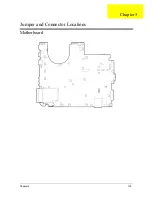
Page 149: ...Chapter 5 139 Motherboard Jumper and Connector Locations Chapter 5 ...
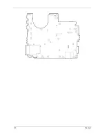
Page 150: ...140 Chapter 5 ...
Page 154: ...144 Chapter 5 ...
Page 156: ...146 Chapter 6 Aspire 8730 8730Z 8530 Series Exploded Diagram ...
Page 188: ...Appendix A 178 ...
Page 192: ...182 Appendix B ...
Page 194: ...184 Appendix C ...

