10
Chapter 1
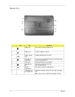
Bottom View
Icon
Item
Description
1
Battery bay
Houses the computer's battery pack.
2
Battery lock
Locks the battery in position.
3
Battery release
latch
Releases the battery for removal.
4
Hard disk bay-
Secondary
Houses the computer's hard disk (secured with screws)
(only for certain models).
5
Subwoofer
Emits low frequency sound output.
6
Hard disk bay-
Main
Houses the computer's hard disk
(secured with screws).
7
Memory
compartment
Houses the computer's main memory.
8
Ventilation slots
and cooling fan
Enable the computer to stay cool, even after prolonged
use.
Note: Do not cover or obstruct the opening of the fan.
Summary of Contents for Aspire 8530 Series
Page 6: ...VI ...
Page 10: ...X Table of Contents ...
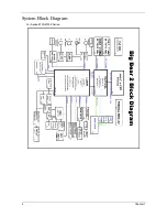
Page 14: ...4 Chapter 1 System Block Diagram For Aspire 8730 8730Z Series ...
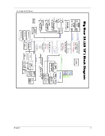
Page 15: ...Chapter 1 5 For Aspire 8530 Series ...
Page 46: ...36 Chapter 1 ...
Page 60: ...50 Chapter 2 ...
Page 77: ...Chapter 3 67 2 Remove the two captive screws securing the hard disk drive cover ...
Page 100: ...90 Chapter 3 19 Disconnect the Media console cable from LEDB1 on the main board ...
Page 118: ...108 Chapter 3 21 Remove the USB board module from the lower case ...
Page 124: ...114 Chapter 3 13 Detach any adhesive tapes and any cable that is glued to the LCD panel ...
Page 125: ...Chapter 3 115 14 Disconnect the FPC cable from the LCD panel ...
Page 142: ...132 Chapter 4 F5h Boot to Mini DOS F6h Clear Huge Segment F7h Boot to Full DOS Code Beeps ...
Page 149: ...Chapter 5 139 Motherboard Jumper and Connector Locations Chapter 5 ...
Page 150: ...140 Chapter 5 ...
Page 154: ...144 Chapter 5 ...
Page 156: ...146 Chapter 6 Aspire 8730 8730Z 8530 Series Exploded Diagram ...
Page 188: ...Appendix A 178 ...
Page 192: ...182 Appendix B ...
Page 194: ...184 Appendix C ...


