66
Chapter 5
SATA CONN
1: GND
2: SATA1_TX_P
3: SATA1_TX_N
4: GND
5: SATA1_RX_N
6: SATA1_RX_P
7: GND
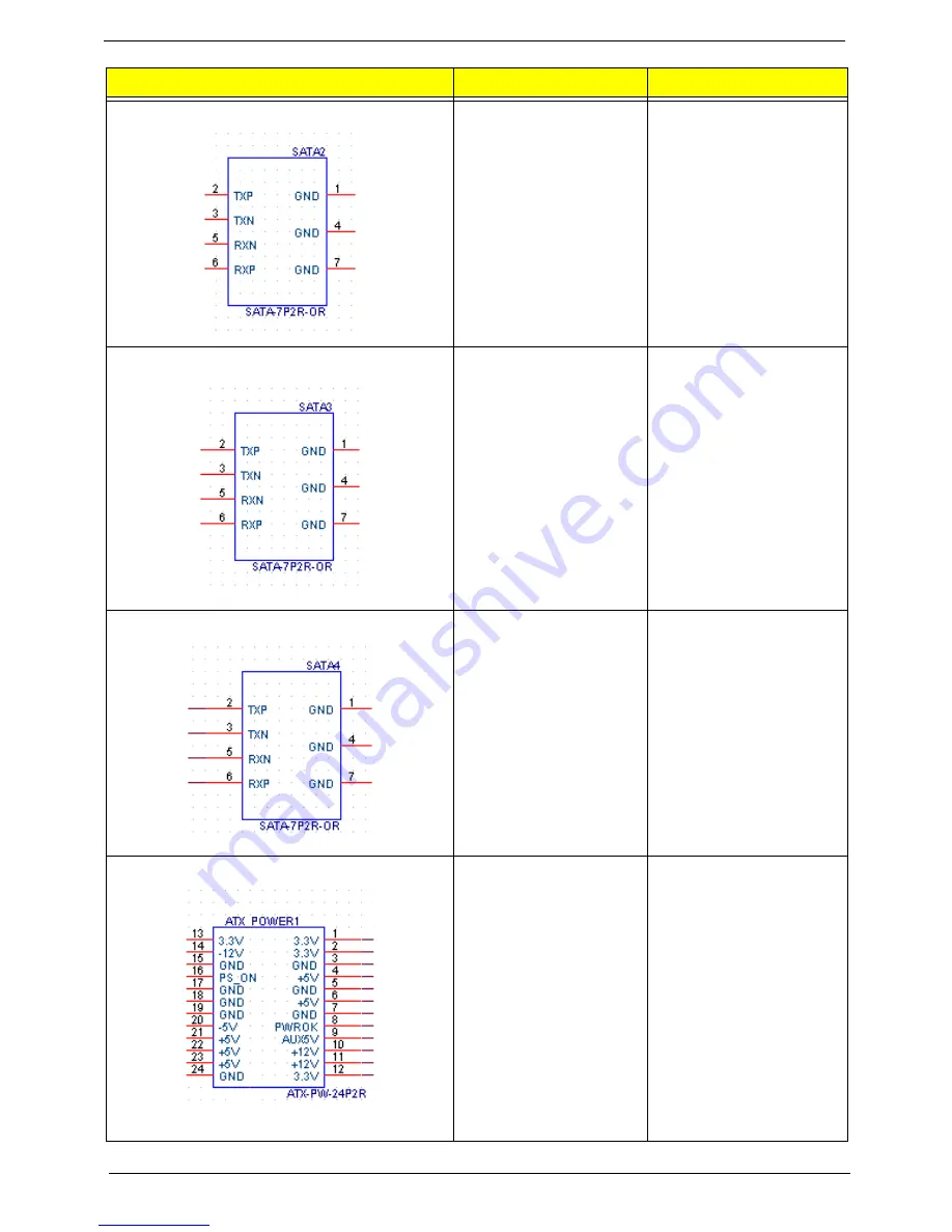
SATA CONN
1: GND
2: SATA2_TX_P
3: SATA2_TX_N
4: GND
5: SATA2_RX_N
6: SATA2_RX_P
7: GND
SATA CONN
1: GND
2: SATA3_TX_P
3: SATA3_TX_N
4: GND
5: SATA3_RX_N
6: SATA3_RX_P
7: GND
ATX_POWER CONN
1:VCC3 13:VCC3
2:VCC3 14:-12V
3: GND 15:GND
4:VCC 16:ATX_PSON_L
5:GND 17:GND
6:VCC 18:GND
7:GND 19:GND
8:ATX_PWRGD 20:NC
9:5VSB 21VCC
10:+12V 22:VCC
11:+12V 23:VCC
12:VCC3 24:GND
Connector Name
Function
Definition
Summary of Contents for Aspire M3900
Page 1: ...Acer Aspire M3900 Service Guide PRINTED IN TAIWAN ...
Page 13: ...Chapter 1 5 Block Diagram ...
Page 42: ...34 Chapter 3 Removing the TV Card 1 Gently pull the TV card to remove it from the mainboard ...
Page 50: ...42 Chapter 3 3 Pull the bezel away from the chassis ...
Page 57: ...Chapter 3 49 3 Lift the power supply module out of the chassis ...
Page 59: ...Chapter 3 51 4 Pull the card reader out of chassis ...
Page 69: ...Chapter 5 61 M B Placement Jumper and Connector Information Chapter 5 ...
Page 75: ...Chapter 5 67 ATX12V CONN 1 GND 2 GND 3 12V_4P 4 12V_4P Connector Name Function Definition ...


