Hardware Specifications and Configurations
1-15
Using the Keyboard
0
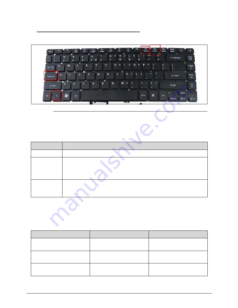
Figure 1-7.
Keyboard Lock Keys
The keyboard has three lock keys which can be toggled on and off. (Table 1-7)
The embedded numeric keypad functions like a desktop numeric keypad. It is indicated by
small characters located on the upper right corner of the key caps. To simplify the keyboard
legend, cursor-control key symbols are not printed on the keys. (Table 1-8)
Table 1-7.
Keyboard Lock Keys
Lock key
Description
Caps Lock
When Caps Lock is on, all alphabetic characters typed are in uppercase.
Num Lock
<Fn> + <F11>
When Num Lock is on, the embedded keypad is in numeric mode. The keys
function as a calculator (complete with the arithmetic ope, -, *, and /).
Use this mode when doing a lot of numeric data entry. A better solution would
be to connect an external keypad.
Scroll Lock
<Fn> + <F12>
When Scroll Lock is on, the screen moves one line up or down when the up or
down arrow keys are pressed respectively. Scroll Lock does not work with
some applications.
Table 1-8.
Embedded Numeric Keypad
Desired access
Num Lock on
Num Lock off
Number keys on embedded
keypad
Type numbers in a normal
manner.
Cursor-control keys on
embedded keypad
Hold <Shift> while using
cursor-control keys.
Hold <Fn> while using
cursor-control keys.
Main keyboard keys
Hold <Fn> while typing letters
on embedded keypad.
Type the letters in a normal
manner.
Summary of Contents for Aspire M5-481PT
Page 1: ...Acer M5 481 481G 481T 481TG SERVICE GUIDE ...
Page 8: ...viii ...
Page 9: ...CHAPTER 1 Hardware Specifications ...
Page 10: ...1 2 ...
Page 54: ...1 44 Hardware Specifications and Configurations ...
Page 55: ...CHAPTER 2 System Utilities ...
Page 56: ...2 2 ...
Page 73: ...Acer M5 481 481G 481T 481TG System Utilities 2 19 Figure 2 19 InsydeFlash ...
Page 83: ...CHAPTER 3 Maintenance Procedures ...
Page 84: ...3 2 ...
Page 91: ...3 9 Figure 3 2 Lower Cover Cabling ID Size Quantity Screw Type A M2 5x5 0 15 ...
Page 95: ...3 13 ID Size Quantity Screw Type M2 5 x 1 x 7 Flat head 2 ...
Page 103: ...3 21 ID Size Quantity Screw Type M2 0 x 2 0 1 ...
Page 105: ...3 23 ID Size Quantity Screw Type M2 0 x 2 0 1 ...
Page 113: ...3 31 ID Size Quantity Screw Type A M2 0 x 2 0 2 B M2 0 x 2 0 2 ...
Page 116: ...3 34 Figure 3 2 Fan Thermal Assembly Removal ...
Page 118: ...3 36 ID Size Quantity Screw Type A M2 0 x 0 5 x 7 0 Flathead 3 B M2 0 x 0 5 x 7 0 Flathead 3 ...
Page 122: ...3 40 ID Size Quantity Screw Type A M2 0 x 0 5 x 7 0 flathead 2 ...
Page 132: ...3 50 ID Size Quantity Screw Type A M2 5x5 0 15 ...
Page 138: ...3 56 Figure 3 2 Audio Board Screws Removal ID Size Quantity Screw Type M2 0 x 3 0 2 ...
Page 143: ...3 61 ID Size Quantity Screw Type M2 0 x 2 0 1 ...
Page 148: ...3 66 Figure 3 3 MIC Cable Positioning ...
Page 153: ...3 71 Figure 3 2 Fan Thermal Screw Removal 1 3 2 4 5 6 ...
Page 159: ...3 77 Figure 3 3 LVDS Alignment ...
Page 162: ...3 80 ID Size Quantity Screw Type M2 5 x 3 0 3 ...
Page 166: ...CHAPTER 4 Troubleshooting ...
Page 167: ...4 2 ...
Page 188: ...CHAPTER 5 Jumper and Connector Locations ...
Page 189: ...5 2 ...
Page 191: ...5 4 ...
Page 192: ...CHAPTER 6 FRU Field Replaceable Unit List ...
Page 193: ...6 2 ...
Page 206: ...CHAPTER 7 Model Definition and Configuration ...
Page 207: ...7 2 ...
Page 233: ...7 28 Model Definition and Configuration ...
Page 234: ...CHAPTER 8 Test Compatible Components ...
Page 235: ...8 2 ...
Page 243: ...8 10 Test Compatible Components ...
Page 244: ...CHAPTER 9 Online Support Information ...
Page 245: ...9 2 ...
Page 247: ...9 4 Online Support Information ...


