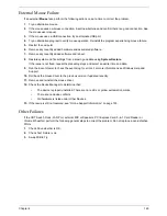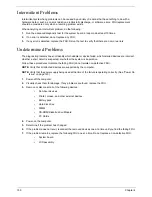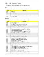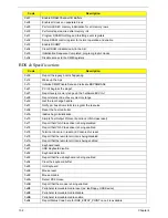
Chapter 5
159
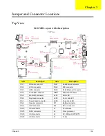
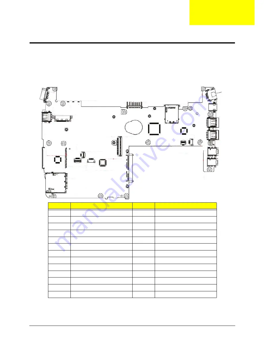
Jumper and Connector Locations
Top View
Item
Description
Item
Description
CN1
SD card connector
CN21
Headphone connector
CN2
LVDS connector
CN22
MIC connector
CN3
LED connector
CN23
RJ45 Ethernet Connector
CN4
TouchPad connector
JSMI1
SIM card connector
CN5
Bluetooth connector
LED1
HDD LED
CN6
Keyboard connector
LED2
Num Lock LED
CN7
Power board connector
LED3
Caps Lock LED
CN8
Speaker connector
PJ1
Battery connector
CN9
CRT connector
PJ2
DC-in connector
CN10
USB connector
U1
Card reader
CN15
SATA connector
U2
Clock generator
CN19
USB connector
U4
EC Winbond WPCE775
CN20
USB connector
U7
Codec
ZG8 MB Layout with description
TOP view
U1
C
a
rd Re
a
der
Re
a
lte
k
RT
SS
I59
CN3
LFD connector
CN1
S
D C
a
rd connector
CN5
Bluetooth connector
CN2
Cloc
k
Gener
a
tor
CN4
TouchP
a
d connector
CN15
SA
T
A
connector
CN8
S
pe
ak
er connector
CN21
He
a
dPhone
CN7
Po
w
er bo
a
rd connector
CN22
MIC
U4
EC
Winbo
a
nd WPCE775
U7
Codec
Re
a
lte
k
A
LC272
CN20
U
S
B
CN19
U
S
B
PJ2
DC-IN
CN23
RJ45
J
S
MI1
S
IM c
a
rd connector
PJ1
B
a
ttery connector
LED3
C
a
ps Loc
k
LED
LED1
HDD LED
LED2
Nu
m
ber LED
CN2
LVD
S
connector
CN10
U
S
B
CN9
CRT
CN6
Keybo
a
rd connector
Chapter 5
Summary of Contents for Aspire One AO531h
Page 6: ...VI ...
Page 10: ...X Table of Contents ...
Page 30: ...20 Chapter 1 ...
Page 48: ...38 Chapter 2 ...
Page 63: ...Chapter 3 53 8 Disconnect the FFC and remove the Keyboard ...
Page 69: ...Chapter 3 59 4 Remove the board from the Upper Cover ...
Page 82: ...72 Chapter 3 5 Disconnect the Bluetooth cable from the module ...
Page 89: ...Chapter 3 79 4 Lift the CPU Fan clear of the Mainboard ...
Page 101: ...Chapter 3 91 4 Lift up the bezel and remove it from the LCD Module ...
Page 107: ...Chapter 3 97 7 Disconnect the cable from the LCD panel as shown ...
Page 138: ...128 Chapter 3 6 Insert the FFC in to the Button Board and close the locking latch ...
Page 202: ...192 Appendix B ...
Page 204: ...194 Appendix C ...
Page 208: ...198 ...

