Appendix A
176
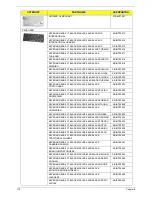
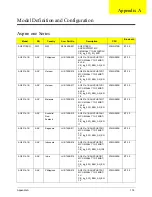
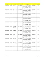
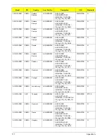
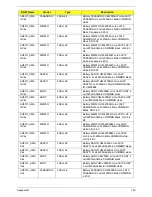
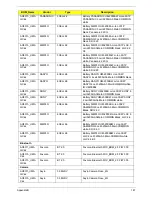
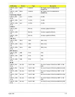
AO531h-1BG
WW
GCTWN
S2.S650B.003
AO531h-1BG
AOXPHSTWW1 MC
UMAGCkk 1*1G/160/BT/3L/
CB_bg_0.3D_3G_ENX1_U
NDP-1
ATMN280B
BT 2.0
AO531h-1BG
WW
WW
S2.S650B.004
AO531h-1BG
AOXPHSTWW1 MC
UMAGCkk 1*1G/160/BT/3L/
CB_bg_0.3D_3G_EN11_UN
DP-1
ATMN280B
BT 2.0
AO531h-1BG
WW
WW
S2.S650B.009
AO531h-1BG
AOXPHSTWW1 MC
UMAGCkk 1*1G/160/BT/
6L2.6/
CB_bg_0.3D_3G_AN_EN11
_UNDP-1
ATMN280B
BT 2.0
AO531h-1BG
WW
WW
S2.S650B.006
AO531h-1BG
AOXPHSTWW1 MC
UMAGCkk 1*1G/160/BT/
6L2.6/
CB_bg_0.3D_3G_EN11
ATMN280B
BT 2.0
AO531h-1BG
WW
WW
S2.S650B.002
AO531h-1BG
AOXPHSTWW1 MC
UMAGCkk 1*1G/160/BT/3L/
CB_bg_0.3D_3G_EN11
ATMN280B
BT 2.0
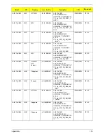
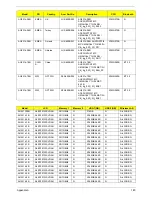
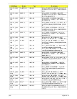
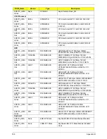
AO531h-0BG
AAP
Australia/
New
Zealand
LU.S650B.052
AO531h-0BG
AOXPHSTAU1 MC
UMAGCkk 1*1G/160/BT/3L/
CB_bg_0.3D_3G_BAG_AN
_EN11
ATMN270B
BT 2.0
AO531h-1BG
AAP
Philippines
LU.S650B.051
AO531h-1BG
AOXPHSTPH1 MC
UMAGCkk 1*1G/160/BT/3L/
CB_bg_0.3D_3G_BAG_AN
_EN12
ATMN280B
BT 2.0
AO531h-1BG
AAP
Thailand
LU.S650B.050
AO531h-1BG
AOXPHSTTH1 MC
UMAGCkk 1*1G/160/BT/3L/
CB_bg_0.3D_3G_BAG_AN
_TH22
ATMN280B
BT 2.0
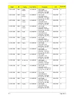
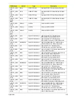
AO531h-1BG
WW
GCTWN
S2.S650B.010
AO531h-1BG
AOXPHSTWW1 MC
UMAGCkk 1*1G/160/BT/
6L2.6/
CB_bg_0.3D_3G_AN_ENX
1_UNDP-1
ATMN280B
BT 2.0
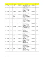
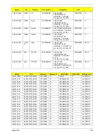
AO531h-1BG
AAP
Singapore
LU.S650B.049
AO531h-1BG
AOXPHSTSG1 MC
UMAGCkk 2*1G/160/BT/3L/
CB_bg_0.3D_3G_BAG_EN
11
ATMN280B
BT 2.0
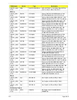
AO531h-0BG
AAP
Singapore
LU.S650B.048
AO531h-0BG
AOXPHSTSG1 MC
UMAGCkk 1*1G/160/BT/3L/
CB_bg_0.3D_3G_BAG_EN
11
ATMN270B
BT 2.0
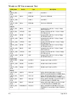
Model
RO
Country
Acer Part No
Description
CPU
Bluetoo
th
Summary of Contents for Aspire One AO531h
Page 6: ...VI ...
Page 10: ...X Table of Contents ...
Page 30: ...20 Chapter 1 ...
Page 48: ...38 Chapter 2 ...
Page 63: ...Chapter 3 53 8 Disconnect the FFC and remove the Keyboard ...
Page 69: ...Chapter 3 59 4 Remove the board from the Upper Cover ...
Page 82: ...72 Chapter 3 5 Disconnect the Bluetooth cable from the module ...
Page 89: ...Chapter 3 79 4 Lift the CPU Fan clear of the Mainboard ...
Page 101: ...Chapter 3 91 4 Lift up the bezel and remove it from the LCD Module ...
Page 107: ...Chapter 3 97 7 Disconnect the cable from the LCD panel as shown ...
Page 138: ...128 Chapter 3 6 Insert the FFC in to the Button Board and close the locking latch ...
Page 202: ...192 Appendix B ...
Page 204: ...194 Appendix C ...
Page 208: ...198 ...

