90
Chapter 3
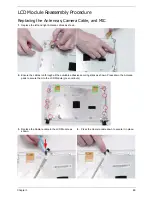
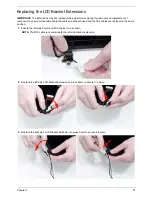
5.
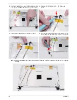
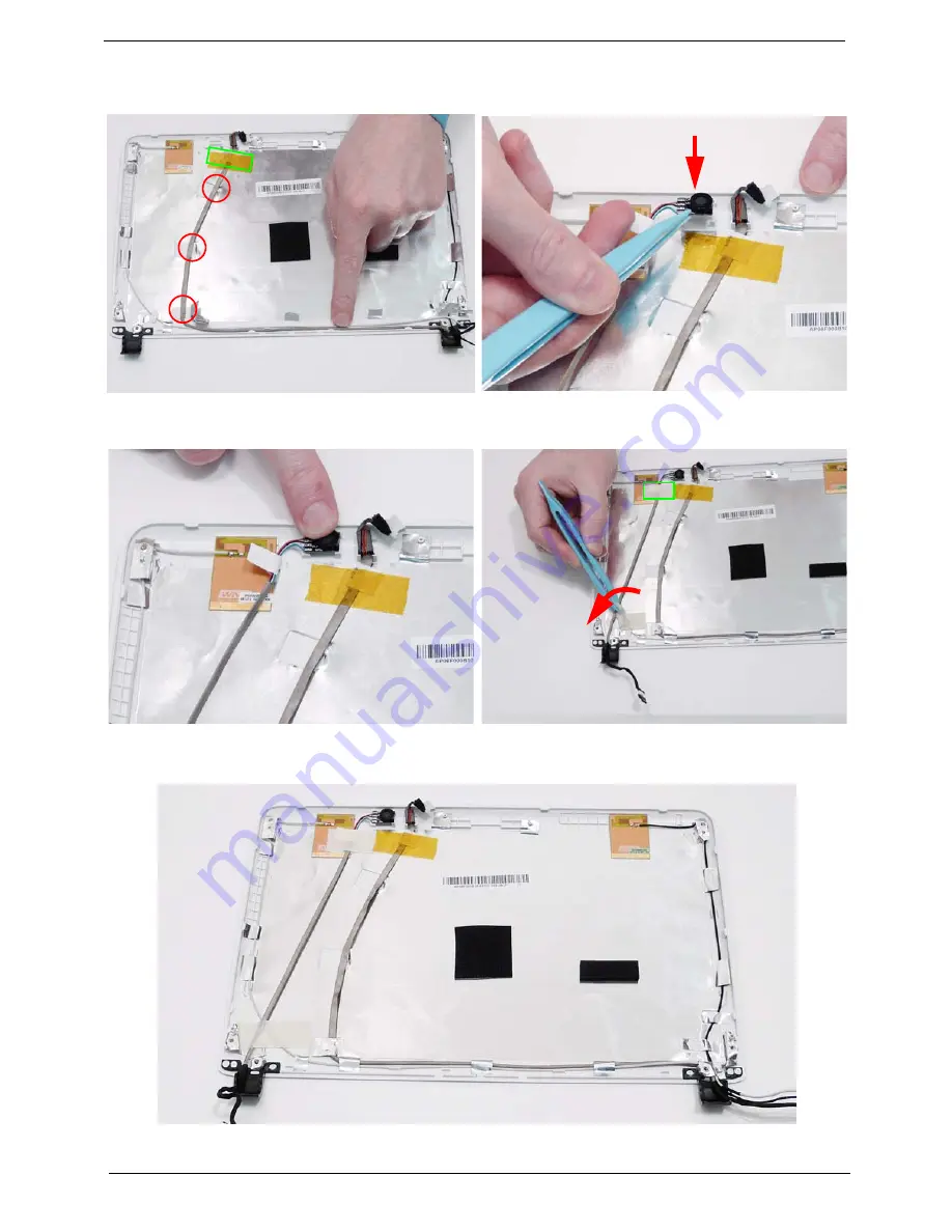
Run the cable as shown using all the available cable
clips and replace the adhesive strip (green callout).
6.
Replace the MIC Board in the LCD Module as
shown.
7.
Press the MIC Board down to secure it in place.
8.
Run the MIC cable along the LCD Module as shown
and replace the adhesive strips to secure it in place.
NOTE:
The LCD Module appears as shown when the Antennas, Camera Cable, and MIC Board are replaced
correctly.
Summary of Contents for Aspire One AOD150
Page 6: ...VI ...
Page 10: ...X Table of Contents ...
Page 28: ...18 Chapter 1 ...
Page 42: ...32 Chapter 2 5 Flash is complete when the message Flash programming complete displays ...
Page 55: ...Chapter 3 45 4 Lift the Memory cover up to remove 5 Lift the WLAN cover up to remove ...
Page 67: ...Chapter 3 57 7 Lift the Upper Cover clear of the computer ...
Page 78: ...68 Chapter 3 4 Lift the USB Board clear of the computer rear edge first ...
Page 80: ...70 Chapter 3 4 Turn the Bluetooth Module over and disconnect the Bluetooth cable ...
Page 83: ...Chapter 3 73 9 Turn the Mainboard over and disconnect the Power Cable ...
Page 85: ...Chapter 3 75 5 Remove the Speaker Module from the Lower Cover ...
Page 110: ...100 Chapter 3 4 Secure the Speaker Module cable in place with the adhesive strips ...
Page 220: ...Appendix A 210 ...
Page 228: ...218 Appendix C ...

