Chapter 3
51
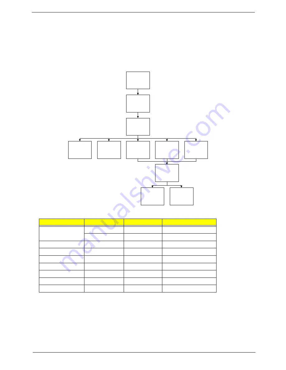
Main Unit Disassembly Process
IMPORTANT:
Cable paths and positioning may not represent the actual model. During the removal and
replacement of components, ensure all available cable channels and clips are used and that the cables are
replaced in the same position.
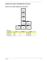
Main Unit Disassembly Flowchart
Screw List
Step
Screw
Quantity
Part No.
Upper Cover
M2*3
3
86.S5502.001
M2*6
11
86.S5502.002
Power Board
M2*3
1
86.S5502.001
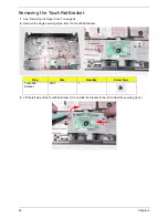
TouchPad Bracket
M2*3
1
86.S5502.001
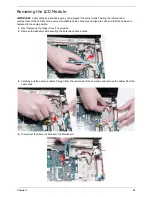
LCD Module
M2*6
2
86.S5502.002
USB Board
M2*3
1
86.S5502.001
Mainboard
M2*3
1
86.S5502.001
Speaker Module
M2*3
2
86.S5502.001
Thermal Module
M2*3
2
86.S5502.001
Remove External
Modules before
proceeding
Remove
Mainboard
Remove
LCD Module
Remove
Keyboard
Remove
Upper Cover
Remove
Thermal Module
Remove
USB Board
Remove
TouchPad
Bracket
Remove
Power Board
Remove
Bluetooth Module
Remove
Speaker Modue
Summary of Contents for Aspire One AOD150
Page 6: ...VI ...
Page 10: ...X Table of Contents ...
Page 28: ...18 Chapter 1 ...
Page 42: ...32 Chapter 2 5 Flash is complete when the message Flash programming complete displays ...
Page 55: ...Chapter 3 45 4 Lift the Memory cover up to remove 5 Lift the WLAN cover up to remove ...
Page 67: ...Chapter 3 57 7 Lift the Upper Cover clear of the computer ...
Page 78: ...68 Chapter 3 4 Lift the USB Board clear of the computer rear edge first ...
Page 80: ...70 Chapter 3 4 Turn the Bluetooth Module over and disconnect the Bluetooth cable ...
Page 83: ...Chapter 3 73 9 Turn the Mainboard over and disconnect the Power Cable ...
Page 85: ...Chapter 3 75 5 Remove the Speaker Module from the Lower Cover ...
Page 110: ...100 Chapter 3 4 Secure the Speaker Module cable in place with the adhesive strips ...
Page 220: ...Appendix A 210 ...
Page 228: ...218 Appendix C ...

