Chapter 1
3
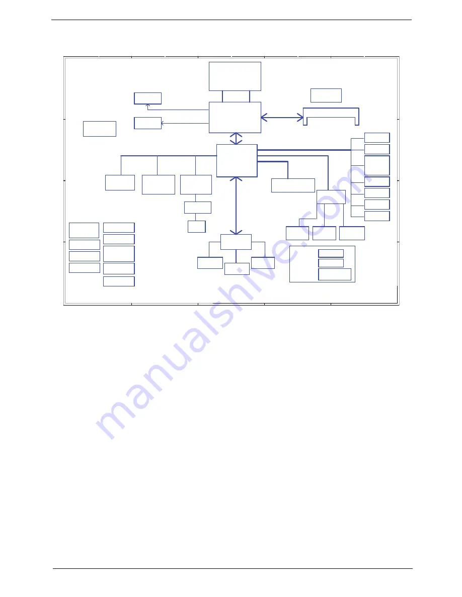
System Block Diagram
A
A
B
B
C
C
D
D
E
E
1
1
2
2
3
3
4
4
X2 mode
Touch Pad
CRT Conn
LPC BUS
page 20
27x27mm
)
3
6
..
0
(
#
D
_
H
)
1
3
..
3
(
#
A
_
H
page 24
page 14
page 21
Int.KBD
page 25
400/533MHz
ALC272
DMI
Diamondville SC
FSB
Transfermer
Power ON/OFF
& LED CONN
page 25
page 13
FCBGA8
DDRII-SO-DIMM
Calistoga GSE
FCBGA998
SPI ROM
page 4
1.8V DDRII 400/533
page 4,5
page 27
Aralia Codec
Memory BUS(DDRII)
31x31mm
page 6,7,8,9,10
ICH7M
BGA652
Thermal Sensor
page 11
page 15,16,17,18
page 27
ENE KBC
KB926
AMP & INT
Speaker
10/100 Ethernet
AR8114A
page 24
SDIO CONN
MINI Card x2
PCI-Express
EMC1402
LCD Conn.
page 27
page 19
LVDS
page 28
USB Port X1
SPI
INT DMIC CONN
HeadPhone &
MIC Jack
RGB
page 22
I/O Board X2
page 22
to I/O board
CONN
page 24
RJ45
DC/DC Interface
3VALW/5VALW
1.8V/VCCP
1.5VS/0.9VS/
2.5VS
CPU_CORE
Clock Generator
CK505
page 12
page 21
page 13
page 26
page 29
page 37
page 33
page 35
page 36
USB
BlueToothX1
CMOS CAM
page19
page13
HDA
page 31
page 32
page 34
CHARGER
DC IN
BATT IN
437Pins
22x22mm
page 22
to I/OBoard CONN
SATA
WLANX1
page19
WWANX1
page19
RTS5159E
JP7
SATA CONN
USB Port X2
USB Card Reader
x1 RTS5159E
I/O board
Summary of Contents for Aspire One AOP531h
Page 6: ...VI ...
Page 10: ...X Table of Contents ...
Page 41: ...Chapter 2 31 Clear User or Supervisor Password 1 Open the RAM door 2 Short RTC_RST ...
Page 83: ...Chapter 3 73 Pull the cable completely away from the bezel ...
Page 95: ...Chapter 3 85 4 Replace the four screws and screw caps ...
Page 107: ...Chapter 3 97 The upper cover is now ready to attach to the bottom cover ...
Page 109: ...Chapter 3 99 Turn the unit over and affix the five screws in the top cover ...
Page 115: ...Chapter 3 105 Replacing the SIMM Card Insert the SIMM Card into the slot ...
Page 130: ...120 Chapter 4 ...
Page 138: ...128 Chapter 4 ...
Page 152: ...142 Chapter 6 ...
Page 153: ...Chapter 6 143 ...
Page 267: ...257 Appendix A ...
Page 268: ...Appendix A 258 ...
Page 274: ...264 Appendix B ...
Page 276: ...266 Appendix C ...
Page 280: ...270 ...


