Chapter 3
69
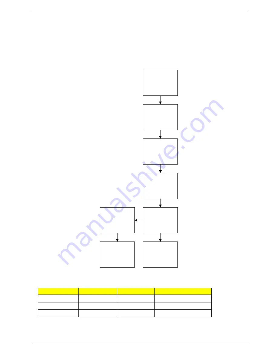
LCD Module Disassembly Process
IMPORTANT:
Cable paths and positioning may not represent the actual model. During the removal and
replacement of components, ensure all available cable channels and clips are used and that the
cables are replaced in the same position.
LCD Module Disassembly Flowchart
Screw List
Step
Screw
Quantity
Part No.
LCD Bezel
M2*4
4
MA0000069G0
LCD Panel
M2*4
2
MA0000069G0
LCD Brackets
M2*4
4
MA0000069G0
Re
m
ove
LCD Brackets
Re
m
ove
Camera Module
Re
m
ove
LCD FPC Cable
Re
m
ove LCD
P
a
nel
f
ro
m
M
a
in
Unit be
f
ore
proceedin
g
Re
m
ove
LCD Panel
Re
m
ove
Antennas
Re
m
ove
Microphone
Re
m
ove
LCD Bracket
Bezel
Summary of Contents for Aspire One AOP531h
Page 6: ...VI ...
Page 10: ...X Table of Contents ...
Page 41: ...Chapter 2 31 Clear User or Supervisor Password 1 Open the RAM door 2 Short RTC_RST ...
Page 83: ...Chapter 3 73 Pull the cable completely away from the bezel ...
Page 95: ...Chapter 3 85 4 Replace the four screws and screw caps ...
Page 107: ...Chapter 3 97 The upper cover is now ready to attach to the bottom cover ...
Page 109: ...Chapter 3 99 Turn the unit over and affix the five screws in the top cover ...
Page 115: ...Chapter 3 105 Replacing the SIMM Card Insert the SIMM Card into the slot ...
Page 130: ...120 Chapter 4 ...
Page 138: ...128 Chapter 4 ...
Page 152: ...142 Chapter 6 ...
Page 153: ...Chapter 6 143 ...
Page 267: ...257 Appendix A ...
Page 268: ...Appendix A 258 ...
Page 274: ...264 Appendix B ...
Page 276: ...266 Appendix C ...
Page 280: ...270 ...


