Chapter 3
51
Removing the LCD Module
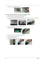
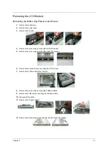
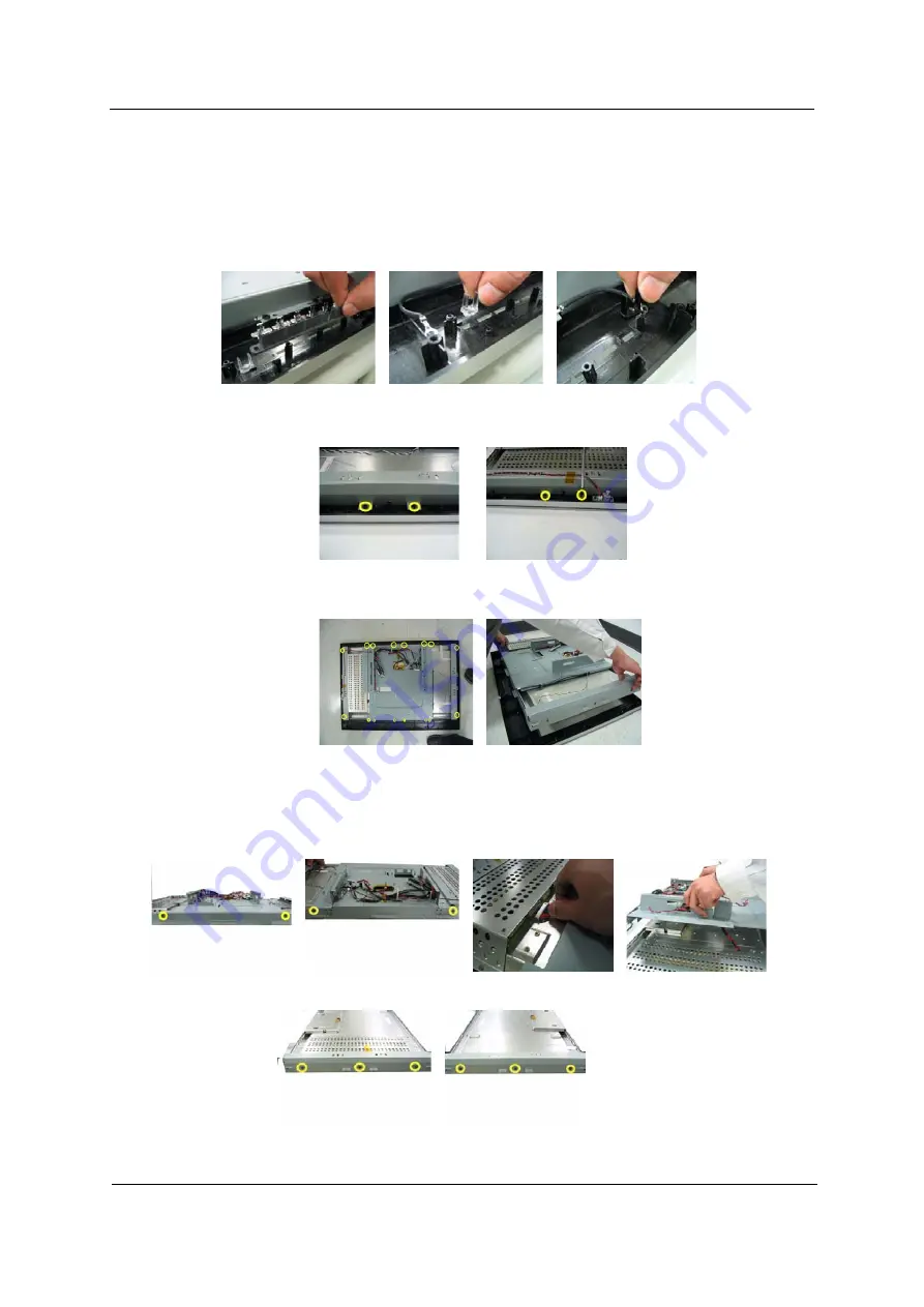
Removing the Button Key/Power Lens/IR Lens
1.
Remove the button key.
2.
Remove the power lens.
3.
Remove the IR lens.
4.
Remove the two screws securing the left LCD bracket.
5.
Remove the two screws securing the right LCD bracket.
6.
Remove the sixteen screws securing the LCD module.
7.
Remove the LCD module from the unit.
8.
Remove the two screws securing the chassis middle.
9.
Remove the other screw securing the chassis middle.
10.
Disconnect the cable.
11.
Remove the chassis middle.
12.
Remove the three screws securing the left and right LCD bracket.
Summary of Contents for AT3201W
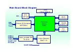
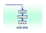
Page 4: ...LCD Main Board Block Diagram ...
Page 8: ...OSD On Screen Display Scanning the channels First step Ask user to select the language of OSD ...
Page 9: ......
Page 10: ......
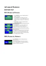
Page 11: ...Advanced Features PIP PBP POP PIP Picture in Picture PBP Picture by Picture ...
Page 12: ...POP Picture on Picture ...
Page 23: ...52 Chapter 3 ...
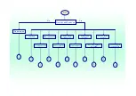
Page 24: ...AT3201W Troubleshooting Guideline ...
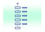
Page 32: ...3 3 Button Board I O Board Main Board END Replacement Replacement Replacement N G N G N G ...
Page 33: ...4 Main Board END Replacement N G ...
Page 34: ...5 5 IR Cable IR board Main Board END Replacement Replacement Replacement N G N G N G ...
Page 35: ...6 IO Board Main Board END Replacement Replacement N G N G ...
Page 36: ...7 7 Button Cable Button Board Main Board END Replacement Replacement Replacement N G N G N G ...
Page 37: ...8 Power Board Main Board END Replacement Replacement N G N G ...


