background image

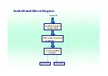
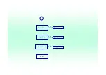
Audio Processor

NJW1165M

Audio Amplifier

TA2024

SRS Audio Processor

NJM2700

SPEAKER-L

SPEAKER-R

Audio IN

Audio Board Block Diagram

Summary of Contents for AT3201W

Page 1: ...ro SCART RGB for Video S Video R G B and Audio z 21 pin Euro SCART YUV RGB for Video S Video YPbPr YCbCr RGB and Audio z RCA jack YUV and CVBS for YPbPr YCbCr Video and Audio z S Din for S Video z 15 pin D Sub for VGA z 24 pin DVI HDCP for DVI D z DIN45325 IEC169 2 Terminal for TV CATV input z 3 5 mm Earphone jack for Audio Line input z 3 5 mm Earphone jack for Audio Line output Video Functions z ...

Page 2: ...ibility Multi Sound system z NICAM z FM Stereo A2 Power Source z Input voltage 90 264 V 47 63 Hz z Input current 2 3 A z Power consumption 210 Watts z Stand by 5 Watts Max Remote controllers z Multi function remote controller Speaker z Internal speaker 10 W x 2 stereo volume adjustable Others z On screen display adjustment function ISP In System Programming function available for revising driver e...

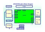
Page 3: ...ck Diagram System Block Wiring Diagram I O Board Scart YUV Scart RGB Tuner SPEAKER Recever IR Key Board I O Board Second SPEAKER S Video IN CVBS IN YUV IN INVERTER PANEL Board AUDIO Board POWER MAIN Board ...

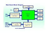
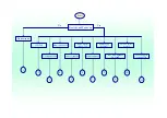
Page 4: ...LCD Main Board Block Diagram ...

Page 5: ...r cord 1 Plug the AC cord into the AC input on the back of the set 2 Connect the male plug to the wall outlet as shown Connecting an antenna Plug the outdoor antenna cable lead into the antenna terminal on the back of the TV set as shown ...

Page 6: ...CR AV equipment Connect the SCART cable to the SCART port as shown below Connecting a camera camcorder or video game Connect your camera or camcorder to the Video Audio ports on the bottom of the TV set as shown below ...

Page 7: ...s Connect your headphones to the headphone input port on the bottom of the TV set as shown below Connecting a PC or Notebook Connect your PC or notebook to the D Sub or DVI ports on the bottom of the TV set as shown below ...

Page 8: ...OSD On Screen Display Scanning the channels First step Ask user to select the language of OSD ...

Page 9: ......

Page 10: ......

Page 11: ...Advanced Features PIP PBP POP PIP Picture in Picture PBP Picture by Picture ...

Page 12: ...POP Picture on Picture ...

Page 13: ...ite Channel Scenario Mode No matter OSD menu is on or off user can directly switch the scenario mode If OSD menu is on switching scenario mode doesn t cause the menu off and user can see the related parameters directly on the menu ...

Page 14: ...3 58 M NTSC 4 43 M Japan 50 Hz z TV Systems PAL and SECAM system Receivable Full frequency range From channel E2 48 25 MHz to channel E69 855 25 MHz z YUV inputs YCbCr 480i 576i YPbPr 480p 576p 1080i 720p z VGA and DVI D inputs Horizontal input frequency range 30 KHz to 70 KHz Vertical input frequency range 56 Hz to 85 Hz Max Resolution 1360 x 768 Down Scaling support 1152 x 870 75 Hz 1280 x 960 6...

Page 15: ...n on VGA port The LED shall indicate green color and OSD will show Go Into Power Save within 5 seconds after meet condition of power saving mode This LCD TV shall go into power saving state in 5 seconds later of showing Go Into Power Save The LED shall indicate amber color during power saving mode This LCD TV shall proceed Auto Adjust while VGA or DVI D input is selected and 1 Power up 2 Auto Adju...

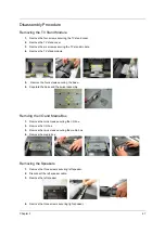
Page 16: ...ing electrostatic discharge T Small Philips screw driver T Philips screwdriver T Plastic flat head screw driver T Tweezers NOTE The screws for the different components vary in size During the disassembly process group the screws with the corresponding components to avoid mismatch when putting back the components When you remove the stripe cover please be careful not to scrape the cover Chapter 3 M...

Page 17: ... all power and signal cables from the system 3 Remove the battery pack NOTE There are several types of screws used to secure the product The screws vary in length Please refer the picture below group the same type of screws together during service disassembling Please also remember the screw location for each screw type If you fasten the screw to the wrong location the screw may be too long to dam...

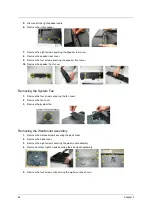
Page 18: ...Remove the four screws securing the base 6 Separate the base and the swivel assembly Remving the I O and Media Box 1 Remove the two screws securing the I O box 2 Remove the I O box 3 Remove the two screws securing the media box 4 Remove the media box Removing the Speakers 1 Remove the three screws securing left speaker 2 Disconnect the left speaker cable 3 Remove the left speaker 4 Remove the thre...

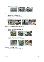
Page 19: ... the speaker front cover Removing the System Fan 1 Remove the four screws securing the fan cover 2 Remove the fan cover 3 Remove the system fan Removing the Wall Mount Assembly 1 Remove the sixteen screws securing the back cover 2 Remove the back cover 3 Remove the eight screws securing the wall mount assembly 4 Remove another eight screws securing the sall mount assembly 5 Remove the four screw n...

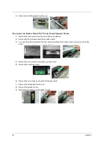
Page 20: ... board 4 Remove the power board Removing the Audio Board and the Main Board 1 Disconnect all cables connected to the audio board 2 Remove the four screws securing the audio board 3 Remove the audio board 4 Remove the two screws securing the mainboard 5 Remove the other four screws securing the mainboard 6 Detach the main board from the unit Removing the Interface Board 1 Remove the two screws secu...

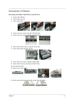
Page 21: ...ecuring the button board 3 Turn over the button and disconnect the cables connected to the button board and remove the button board 4 Remove the two screws securing the ear phone board 5 Remove the ear phone board 6 Remove the two screws securing the left speaker board 7 Remove the left speaker board cover 8 Remove the speaker board 9 Repeat the procedure for right speaker board ƒW TV MODULE ASSY ...

Page 22: ... left LCD bracket 5 Remove the two screws securing the right LCD bracket 6 Remove the sixteen screws securing the LCD module 7 Remove the LCD module from the unit 8 Remove the two screws securing the chassis middle 9 Remove the other screw securing the chassis middle 10 Disconnect the cable 11 Remove the chassis middle 12 Remove the three screws securing the left and right LCD bracket ...

Page 23: ...52 Chapter 3 ...

Page 24: ...AT3201W Troubleshooting Guideline ...

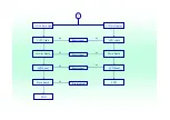
Page 25: ...VERTER POWER B MAIN B CON18 BUTTON B CON11 CON12 IO B CON3 EARPHONE B CON4 CON6 CON7 CON8 AUDIO B CON16 CON17 SPEAKER L SPEAKER R Tuner SCART RGB SCART YUV AT3201W System Block Diagram Sub IO B YUV CVBS S Video ...

Page 26: ...EP169 Video Decoder SAA7119 Video A D Converter MST9883 DDR K4D263238 FLASH AM29LV160 PIC 16F73 LVDS TH63LVDM83R Video Audio SW TA1218 CVBS A CVBS B CVBS C SCART YUV PC Audio SCART RGB VGA YPbPr YCbCr DVI Main Board Block Diagram ...

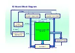
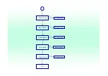
Page 27: ...18 SCART1 RGB PORT SCART2 YUV PORT IO PORT Tuner FQ1216ME Audio Processor MSP34X5G Teletext Connect SCART RGB SCART YUV TV Audio Audio TV Video AV1 Video AV1 Audio AV2 Video AV2 Audio IO Board Block Diagram TV Video Audio ...

Page 28: ...Audio Processor NJW1165M Audio Amplifier TA2024 SRS Audio Processor NJM2700 SPEAKER L SPEAKER R Audio IN Audio Board Block Diagram ...

Page 29: ...n No No 1 LCD Fail 2 4 11 9 7 5 3 Remote Control Fail DDC POP PIP Fail RF No Signal HDTV Fail TV Channel Fail Unit Hang Up Suddenly AV1 AV2 Speaker No Sound Can t Change to Factory Mode AV3 AV4 Speaker No Sound Button Function Fail 10 8 6 Yes Yes ...

Page 30: ...1 1 Power Cord Power Cord Power Cable Power Board Main Bard Audio Board END Replacement Replacement Replacement Replacement Replacement N G N G N G N G N G ...

Page 31: ...2 2 LCD No Back Light LCD No Display CCFT Cable Inverter Board LCD Panel Main Board END END LCD Panel Main Board LCD Cable Replacement Replacement Replacement Replacement N G N G N G N G N G N G N G ...

Page 32: ...3 3 Button Board I O Board Main Board END Replacement Replacement Replacement N G N G N G ...

Page 33: ...4 Main Board END Replacement N G ...

Page 34: ...5 5 IR Cable IR board Main Board END Replacement Replacement Replacement N G N G N G ...

Page 35: ...6 IO Board Main Board END Replacement Replacement N G N G ...

Page 36: ...7 7 Button Cable Button Board Main Board END Replacement Replacement Replacement N G N G N G ...

Page 37: ...8 Power Board Main Board END Replacement Replacement N G N G ...

Page 38: ...9 9 Sub IO Cable Sub IO Cable Sub IO Board Audio Board Main Bard END Replacement Replacement Replacement Replacement N G N G N G N G ...
Page 39: ...10 10 Audio Cable Audio Cable Speaker Audio Board Main Board IO Board END Replacement Replacement Replacement Replacement Replacement N G N G N G N G N G ...
Page 40: ...11 11 Button Cable Button Cable Button Board IO Board Main Board END Replacement Replacement Replacement Replacement N G N G N G N G ...
Page 41: ... made it will not be noted on the printed Service Guide For ACER AUTHORIZED SERVICE PROVIDERS your Acer office may have a DIFFERENT part number code from those given in the FRU list of this printed Service Guide You MUST use the local FRU list provided by your regional Acer office to order FRU parts for repair and service of customer machines NOTE To scrap or to return the defective parts you shou...

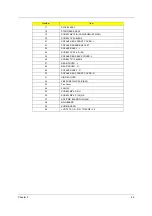
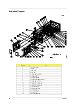
Page 42: ...sy 2 IR Lens 3 Power Lens 4 Button Key 5 SCREW M4 10 B BNI 6 LCD BRACKET 7 SPEAKER BOARD 8 SPEAKER BOARD BRACKET 9 SCREW M3 16 P NI 10 SCREW T4 12 B BLACK 11 SCREW T3 8 P BLACK 12 LCD CHASSIS M 13 EERPHONE BOARD 14 BUTTON BOARD 15 WALL MOUNT 16 BACK COVER ASSY ...

Page 43: ...ER ASSY L 24 SCREW 3 X 20 4 B NI 25 SPEAKER BOX BACK COVER L 26 SCREW T3 12 B BNI 27 REAR COVER L 28 REAR COVER R 29 SPEAKER ASSY R 30 SPEAKER BOX FRONT COVER R 31 HINGE COVER 32 VB5 SCREW M3 22 B BNI 33 Fan Cover 34 FAN 12V 35 SCREW M3 5 P NI 36 SCREW M4 6 P NI S P 37 ADP PWR BOARD W MYLAR 38 MAINBOARD 39 AUDIO BOARD 40 LCD TFT AU 31 5 IN T315XW01 V0 Number Item ...

Page 44: ...mber Accessory REMOTE CONTROL 80 10185 EU 25 M01V7 001 Boards IO BOX MODULE 6M M03V7 001 TUNER MODULE PAL 6M M03V7 002 ADP PWR BOARD W MYLAR 55 M03V7 001 MAINBOARD 55 M03V7 002 AUDIO BOARD 55 M03V7 002 BUTTON BOARD 55 M03V7 004 EERPHONE BOARD 55 M03V7 005 INTERFACE BOARD 55 M03V7 006 ...

Page 45: ...1 STAND BASE ASSY 60 M03V7 002 HINGE COVER 42 M03V7 001 REAR COVER R 42 M03V7 002 REAR COVER L 42 M03V7 003 BACK COVER ASSY 60 M03V7 003 FRONT COVER AASY 60 M03V7 004 WALL MOUNT 33 M03V7 001 SPEAKER BOX BACK COVER R 42 M03V7 004 AT3201W FRU List Picture No Partname And Description Part Number ...

Page 46: ... SPEAKER BOX FRONT COVER L 42 M03V7 007 SPEAKER BOX FRAME 33 M03V7 002 SPEAKER BOARD BRACKET 33 M03V7 003 LCD BRACKET 33 M03V7 004 LCD CHASSIS M 33 M03V7 005 BUTTON KEY 42 M03V7 008 FAN COVER 42 M03V7 009 IR LENS 42 M03V7 010 AT3201W FRU List Picture No Partname And Description Part Number ...

Page 47: ...13 GASKET STICK 47 M03V7 001 Cables POWER CODE ITALY 3P 1 8M 27 M03V7 001 POWER CODE EU 3P 1 8M 27 M03V7 002 POWER CODE UK 3P 1 8M 27 M03V7 003 CABLE MB TO AUDIO 50 M03V7 001 CABLE MB TO POWER 50 M03V7 002 CABLE EARPHONE 50 M03V7 003 AT3201W FRU List Picture No Partname And Description Part Number ...

Page 48: ...TTON 50 M03V7 006 CABLE LINE OUT 50 M03V7 007 CABLE AV3 50 M03V7 008 CABLE BTM TO EARPHONE 50 M03V7 009 CABLE EMI GROUND 50 M03V7 010 CABLE FAN TO POWER 50 M03V7 011 CABLE SPEAKER R 50 M03V7 012 CABLE SPEAKER L 50 M03V7 013 AT3201W FRU List Picture No Partname And Description Part Number ...

Page 49: ...M BLACK 50 M03V7 017 CABLE VB1D PAL 1 8M BLACK 50 M03V7 018 CABLE SCART BLCAK 50 M03V7 019 CABLE RCA YWR 1 8M BLACK 50 M03V7 020 CABLE S LINE 1 8M BLACK 50 M03V7 021 LCD LCD TFT AU 31 5 IN T315XW01 V0 56 M03V7 001 Miscellaneous PE BAG FOR PANEL 47 M03V7 001 AT3201W FRU List Picture No Partname And Description Part Number ...

Page 50: ...AKER ASSY R 23 M03V7 002 SPEAKER ASSY L 23 M03V7 003 Screws SCREW M3 5 P NI 86 M01V7 001 SCREW 4 40 UNC P NI 86 M01V7 009 SCREW M3 16 P NI 86 M01V7 010 VB5 SCREW M3 22 B BNI 86 M03V7 001 SCREW M4 10 B BNI 86 M03V7 002 AT3201W FRU List Picture No Partname And Description Part Number ...

Page 51: ...003 SCREW T4 12 B BLACK 86 M03V7 004 SCREW T4 25 B BNI 86 M03V7 005 SCREW M4 15 B NI WASHER SPRING 86 M03V7 006 SCREW 3 X 20 4 B NI 86 M03V7 007 SCREW M4 6 P NI S P 86 M03V7 008 AT3201W FRU List Picture No Partname And Description Part Number ...

Reviews: