Chapter 4
21
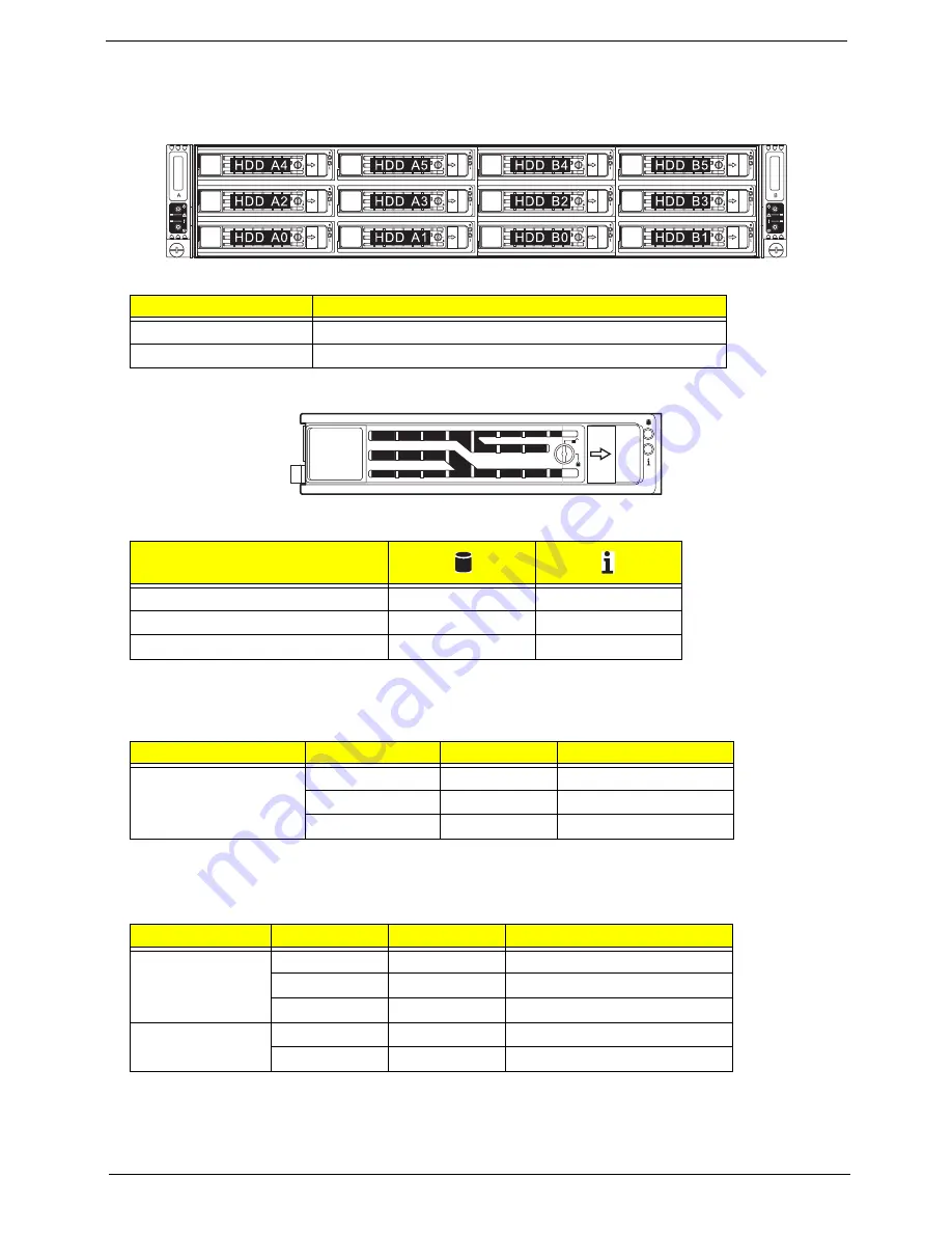
Hard disk drive sequence and LED indicators
The hard drive sequence is as follows:
Drive activity LED indicators are mounted on the hot-plug HDD carrier.
The table below lists the possible drive states.
Rear panel LED indicators
LAN Port LED indicators
Bay no.
Description
Node A HDD A0 to A5
Six 3.5-inch hot-plug drive bays controlled by node A
Node B HDD B0 to B5
Six 3.5-inch hot-plug drive bays controlled by node B
Description
Blue
Red
HDD present no access
Off
Off
HDD access
Blink
Off
LED indicator
LED color
LED state
Status
System ID indicator
N/A
Off
Normal
Blue
On
System identification
Blue
Blinking
IPMI-activated system ID
LED indicator
LED color
LED state
Status
RJ45 LED (Left)
N/A
Off
No connection or 10 Mbps
Green
On
100 Mbps
Amber
On
1000 Mbps
RJ45 LED (Right)
Amber
On
Active connection
Amber
Blinking
Transmit/Receive activity
Summary of Contents for AW2000ht-AW170ht F1
Page 1: ...Acer AW2000ht Service Guide PART NO PRINTED IN TAIWAN ...
Page 18: ...12 Chapter 2 ...
Page 28: ...22 Chapter 4 System block diagram ...
Page 30: ...24 Chapter 5 Mainboard connectors ...
Page 34: ...28 Chapter 5 ...
Page 72: ...66 Chapter 8 ...
Page 89: ...Chapter 10 83 ...
Page 90: ...84 Chapter 10 ...
Page 91: ...Chapter 11 85 Information unavailable BIOS POST Error Messages List Chapter 11 ...
Page 92: ...86 Chapter 11 ...


