background image


Contents 


Important Safety Notice.................................................................................................................................... 3


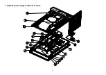
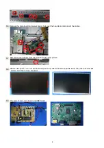
1. Exploded view diagram with list of items ...................................................................................................... 4


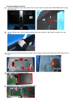
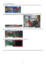
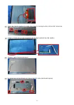
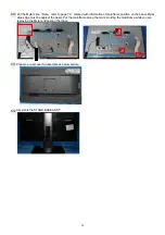
2. Mechanical Instruction ................................................................................................................................. 6


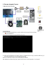
3. Firmware Upgrade Process ....................................................................................................................... 10


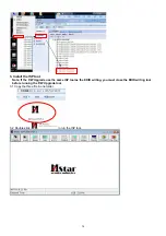
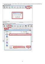
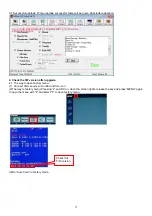
4. Writing EDID Process ................................................................................................................................ 13


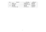
5. FRU (Field Replaceable Unit) List .............................................................................................................. 25


6. Trouble shooting instructions ..................................................................................................................... 25


Summary of Contents for B246HYL

Page 1: ...1 23 8 LCD Monitor ACER B246HYL Service Service Service Acer Monitor B246HYL LIFECYCLE EXTENSION GUIDE ...

Page 2: ...ant Safety Notice 3 1 Exploded view diagram with list of items 4 2 Mechanical Instruction 6 3 Firmware Upgrade Process 10 4 Writing EDID Process 13 5 FRU Field Replaceable Unit List 25 6 Trouble shooting instructions 25 ...

Page 3: ... may create shock fire or other hazards Under no circumstances should the original design be modified or altered without written permission from ACER ACER assumes no liability express or implied arising out of any unauthorized modification of design Servicer assumes all liability FOR PRODUCTS CONTAINING LASER DANGER Invisible laser radiation when open AVOID DIRECT EXPOSURE TO BEAM CAUTION Use of c...

Page 4: ...4 1 Exploded view diagram with list of items ...

Page 5: ...o 4 PANEL 750GBG238F1A13N000 KL 23808 003 6 POWER BOARD PLPCDE321AATI 55 LZ8M2 003 9 MAIN BOARD 756GQDCB0BA6110000 55 LZ8M2 002 18 KEY BOARD KEPCCQKK 55 LXMM2 003 19 USB BOARD USBCQB8 55 LXQM2 005 FFC CABLE 30P 180MM 395G179E30NF91 50 LZ8M2 001 ...

Page 6: ...st the type and size of the tools that would typically can be used to disassemble the product to a point where components and materials requiring selective treatment can be removed Tool Description Screwdriver Phillip head Hexagonal head Penknife ...

Page 7: ...same time Remove the rear cover Use a tool like picture using to open all latches Be careful the position of the key board Disconnect the FFC cable main board to panel tear up all tapes and disconnect lamp power cable power board to panel Turn over the shield Remove the Mylar Unscrew the screws on main board and power board S1 S3 S2 S5 S4 Press ...

Page 8: ...nect the cables Disconnect the speaker from the mainframe as below picture Remove the panel Turn over the bezel and panel unit Lift the bezel to separate it from the panel as below left picture And then remove the panel The power board main board and USB board S7 S8 S6 S9 ...

Page 9: ...9 The bezel and key board S10 ...

Page 10: ...gh the hole as below left picture remarked in red circle Connect all cables as below right picture Use a Philips head screwdriver to tighten the screws till the converter board and main board with shield are firmly attached Prepare a Mylar turn over the shield Put Mylar on the power board Turn over the shield unit Connect the lamp power cable power board to panel and paste the Mylar to the shield ...

Page 11: ... for locking the VGA DVI and DP connectors Prepare a bezel and key board Assemble bezel and key board aim the active position Prepare a panel Put panel into bezel Assemble bezel unit and shield unit Connect the FFC cable main board to panel S8 S9 S6 S7 ...

Page 12: ...ainframe position on the panel Mylar slice edge must be against the bezel Put the mainframe along the mark Holding the mainframe while you are removing the Mylar and pasting the tapes Prepare a rear cover to assemble as below picture Assemble the STAND BASE ASS Y S10 S11 S12 ...

Page 13: ...When insert the USB cable to PC USB port will pop up a Hardware Wizard to help you install the USB driver if you use this ISP board first time it can auto install success by itself Remark The USB driver files path D FTC100103 Mstar FTCUSB INF After installation the USB serial port driver please to check the port Look the properties of my Computer FW Acer_B246HYL_TS UMPO88CDT9_1A1 H1DP ...

Page 14: ...P tool Note If the F W Upgrade use the same ISP tool as the EDID writing you must close the EDID writing tool before running the F W Upgrade tool 3 1 Copy the three file in one folder 3 2 Double click to run the ISP tool ...

Page 15: ...15 3 3 Connect to the monitor Click Connect If the tool communicate with monitor successfully the tool will detect the flash type of monitor 3 4 Load the F W you want to upgrade ...

Page 16: ... 5 Set parameter in Auto window 3 6 Processing of upgrade After clicking Run the tool start to program It is forbided to power off monitor or switch off connection during programming Scr C AOC_ACER B246HYL_TSUMPO88CDT9_1A1H1DP bin 2019 11 21 16 30 14 Scr C AOC_ACER B246HYL_TSUMPO88CDT9_1A1H1DP bin 2019 11 21 16 30 14 ...

Page 17: ...n factory menu 1 Connect VGA source to monitor and turn it on 2 The way to factory menu Pressing e and DC on when the screen lights release the key and press MENU again to open the menu with F and select F to open factory menu 3 Do Auto Color in factory mode Scr C AOC_ACER B246HYL_TSUMPO88CDT9_1A1H1DP bin 2019 11 21 16 30 14 Check this F W version ...

Page 18: ...n off Burn in mode which screen color switches among red green blue and black 5 Troubleshooting 5 1 Can t Entry ISP Mode 1 Check the cables and ISP JIG are connected fluently 2 Click the Dis Con and click Connect again 3 AC off the monitor for a while and retry it 4 Change other vervion ISP program 5 Change ISP JIG or cable 6 Change PC ...

Page 19: ...are the EDID written 3 1 Change the EDID files name as below rule DP EDID WP dat VGA EDID WA dat HDMI EDID WH dat DVI EDID WD dat 3 2 Copy these files to one folder named as ACER B246HYL must contains config ini file 3 3 Copy ACER B246HYL to DDC folder and put DDC and ISP tool together ...

Page 20: ...config as below 4 Run the ISP tool Note If the F W Upgrade use the same ISP tool as the EDID writing you must close the F W Upgrade tool before running the EDID writing tool 4 1 Double click the icon to open the tool ...

Page 21: ...21 4 2 Select the EDID folder 4 3 Load EDID successful B246HYL ...

Page 22: ...22 4 4 Tick the Only connect HDMI and Write SN 4 5 Set other setting as below B246HY L B246HYL ...

Page 23: ...ype in the date and the 22 digit S N and click Debug Information 4 7 Start to writing Click write EDID to start writing When The green PASS appear the process is finished B246HYL B246HYL B246HYL B246HYL B246HYL ...

Page 24: ...tall the the driver of the ISP tool again 2 If it appears all FF it shows that the EDID data of the Main board is empty you must writing the EDID again 5 Troubleshooting 5 1 Can t write 1 AC on the monitor and turn on it Restart the monitor 2 Take apart the monitor and connect the 7pin of EEPROM to GND to diable write protection then write EDID one by one 3 Set the Burn in on last to try again B24...

Page 25: ...E PROVIDERS your ACER office may have a DIFFERENT part number code from those given in the FRU list of this printed Service Guide You MUST use the local FRU list provided by your regional ACER office to order FRU parts for repair and service of customer machines NOTE To scrap or to return the defective parts you should follow the local government ordinance or regulations on how to dispose it prope...

Page 26: ...M2 001 D SUB CABLE 1500mm 089G 725CAA 2A 50 LNY0B 014 DVI CABLE 1500 389G0745LAAF01 50 LXPM2 002 HARNESS 6P 6P CI1406S 220mm 395G801406DF26 50 LZ1M2 001 HARNESS 2P 2P 100mm 395G801402LF01 50 LXQM2 003 SPEAKER 4OHM 2 5W 378G0025518VAB 23 C2XM2 002 ...

Page 27: ...27 BEZEL Q34G7729BQGB1S0130 60 LZ8M2 001 REAR COVER Q34G7730AEM03S0100 60 LZ8M2 004 STAND BASE ASSY Q37G03141010FH 60 LXQM2 003 MAIN FRAME Q15G141930100B 33 LXQM2 001 ...

Page 28: ...28 6 Trouble shooting instructions ...

Reviews: