background image


Chapter 3 

29

3. 

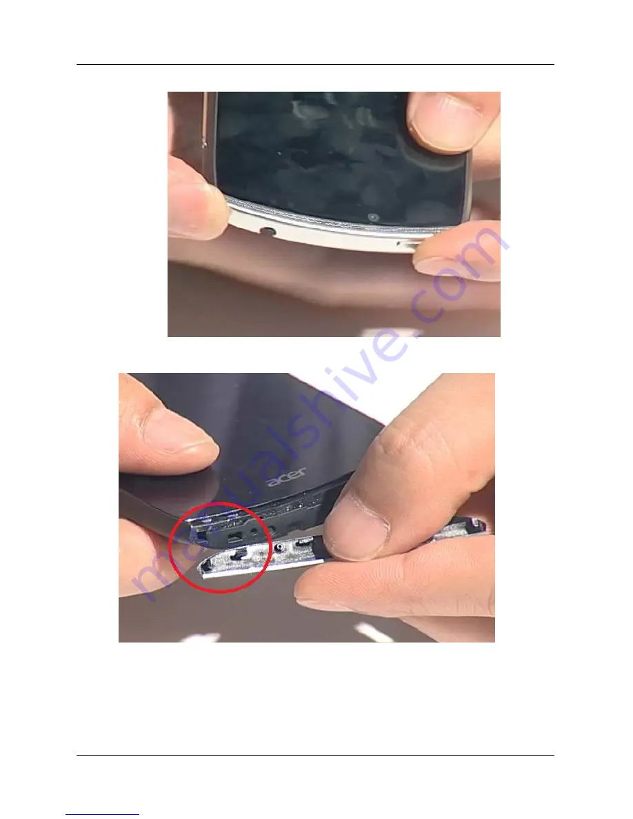
Set the Top Deco to correct position and press power button click feeling to test if power button is assembled correctly. 


4. 

Assemble two sides hooks of Top Deco to S500 


Summary of Contents for CloudMobile S500

Page 1: ...S500 Smartphone Service Guide PRINTED IN TAIWAN Service guide files and updates are available on the ACER CSD web for more information please refer to http csd acer com tw ...

Page 2: ...II Revision History Please refertothetable belowforthe updates madeon the S500 smartphoneserviceguide Date Chapter Updates 28 Aug 2012 Initial release ...

Page 3: ...either expressed of implied with respect to the contents hereof and specially disclaims any warranties ofmerchantability orfitness forany particular purpose Any Acer Incorporated software described in this manual is sold or licensed as is Should the program prove detective following their purchase the buyer are not Acer Incorporated its distributer or it dealer assumes the entire cost of all neces...

Page 4: ...E Gives bits and piecesofadditional Information related tothecurrenttopic WARNING Alerts you toanydamage thatmightresult from doing ornotdoing specific actions CAUTION Gives precautionarymeasures to avoid possible hardware orsoftware problems IMPOTENT Reminds youto do specific actions relevantto the accomplishmentofprocedure ...

Page 5: ...recoveredin this genericservice guide Insuchcases please contactyourregional office orthe responsible personnel channelto provide you with furthertechnical details 2 Please noteWHENORDERINGFRUPARTS thatyou shouldcheck the mostup to date information availableon yourregional web orchannel If forwhateverreason a partnumberchange is made itwill notbenoticed in the printedService Guide For ACER AUTHORI...

Page 6: ...Upgrade SD Download 7 Machine Disassembly and Replacement 11 Diagnostics 31 Serial Number Definition 54 FRU Field Replaceable Unit List 55 S500 SmartphoneExploded Diagram 55 S500 SmartphoneSpare PartsList 56 Online Support Information 60 ...

Page 7: ...tions HSPA EU 2100 1900 900 MHZ USSKU 2100 1900 850 MHz HSPA withoutdiversityantenna HSPA Cat 14 DL21 Mbps UL11 Mbps Quad Bands GSM 850 900 1800 1900MHz GPRSClass12 EDGEClass12 MMS SMS Wireless LAN IEEE802 11a b g n supportWAPIin China SKU SupportWiFi direct Wireless Display AndcanuseA9as a touch PAD to controlWireless Displaycontents GPS GPS A GPSwith SUPL Bluetooth Bluetooth 3 0 HS WCN3660 Camer...

Page 8: ... Buttons Android button Sidekeys Volume Up Down PowerButton Camera Button Power Voltage range frequency 100 240VAC 50 60 HZ DCAdaptor 5V 1A Micro USB Software pre loaded AcerUpdate Google Service Support DocumentViewersupportformail attachment OMADRM Dolbymobile Flash 1Xsupportin Browser acerFOTA GSM GPRS EDGE WCDMA HSDPA HSDPA data connection service AcerExclusiveApplications Power IME T9 orSwift...

Page 9: ...Chapter 1 3 System Block Diagram ...

Page 10: ...on off 5 Earphone jack 3 5 mm headsetjack connecttothe stereo headset 6 Flash LED To flash atthe objective when triggering thecamera function 7 Main camera 8MPCamera withAutoFocus withone LEDflashlight 8 Microphone AElectricsensorthatconvertssound into anelectrical signal 9 Speaker Emits audiofromyoursmartphone suitable fornormaluse 10 Volumekey Increases ordecreases thephone volume 11 Top cover T...

Page 11: ...ble battery pack ACinputvoltage 100 240 Vac 50 60Hz ACinputcurrent 1A DCoutputvoltage 5Vdc typical DCoutputcurrent 1A typical Fullcharge time 1 hourto reach 60 when instandbymode Talk time 3GTalkTime 6 5hours Standby 3GStand by 355hours Camera Item Specification Type Main camera 8MPCamerawithAuto Focuswith oneLEDflashlight Frontcamera HD 1280x720 Fixed Focuscamera GPS Item Specification Chipset Qu...

Page 12: ......

Page 13: ...ortROMimageupgradebetween differentSKUs SupportROMimageupgradewith defaultNVitemupdate Supportdisplayimage downloadprogress baruponscreen Supportimagefile integritycheck Abstract This document will descript how to use SD card to upgradeAcer S500 images SD SDs How to perform SD download 1 Double click SD SDs Copy update zip from SD SDs to SD Card 2 Device turn off Chapter 2 ...

Page 14: ... down and power key 5 Device Vibrated 6 Release all key and press volume up and hold volume up 7 Device vibrated 8 Release all key to launch boot menu 9 Press Volume Up Down to select Apply update from external SD card and press Power Key trigger selection ...

Page 15: ...ess Volume Up Down to select update zip and press Power Key to start update 11 After showing Install from sdcard complete Press Volume Up Down to select reboot system now and press Power Key to reboot and finish update ...

Page 16: ......

Page 17: ...oundingstrap and conductive matto preventelectrostaticdischarge Aclean dry lint freecloth topreventdamage to the LCDduring disassembly Plasticpryless thanorequalto 0 96mm thickness Tweezers plastic and metal NOTE 1 The screws forthe differentcomponents varyinsize During the disassemblyprocess groupthescrews with the corresponding componentsto avoidmismatch whenputtingback the components 2 The scre...

Page 18: ...witha clean dry lint free clothto protectthe LCDpanel 4 Places the systemona flat stablesurface Disassembly Process The disassemblyprocess is dividedintothe following sections Externalcomponentdisassembly Main unitdisassembly The following flowcharts providedinsucceeding disassemblysectionsillustrate the entiredisassemblysequence Observetheorderof the sequence toavoiddamageto anyofthehardware comp...

Page 19: ...Chapter 3 13 External Module Disassembly Process External Module Disassembly Flowchat NOTE Items enclosedwith brokenlines are optionalandmaynotbe present Neededtools ...

Page 20: ...Chapter 3 14 Main Unit Disassembly Process Removing the Battery Cover 1 Remove batterycoverfrom gap atMicroUSBsideofphone ...

Page 21: ...Chapter 3 15 Removing the Battery 1 Remove the battery Removing the SIM Card and Micro SD Card NOTE The Mini SDCard is anoptionalitem and maynotbe present 1 Pull outthe SIMcard MicroSDCard ...

Page 22: ...Chapter 3 16 Removing Rear Case Screws 1 Remove below9pcs rearcasescrews ...

Page 23: ...the Deco Top Deco Down 1 Insertpickfromthegapbetween powerkeyand rearcaseand remove DecoTop When remove DecoTop be carefulpowerkeydropped 2 Insertthepickintothetwo area gaps between rearcase and Deco Down and remove DecoDown ...

Page 24: ...Chapter 3 18 Removing rear case 1 Release the hookatthe bottom ofrearcaseandpull up the rearcase to preventto hookagain ...

Page 25: ...Chapter 3 19 2 InsertpickfromtheareaofMicroSDslotto releasethehook 3 Release the hooknearSIMarea ...

Page 26: ...Chapter 3 20 4 Open and remove the whole rearcase Removing Speaker 1 Release two connectors byplastic tweezers ...

Page 27: ...Chapter 3 21 2 Remove speaker ...

Page 28: ...Chapter 3 22 Removing MB 1 Release fourcable connectors andonescrew ...

Page 29: ...Chapter 3 23 2 Insertpickto the area showed inbelowphoto then raiseupand remove the MB Removing Camera Sensor module Receiver and back camera module directly ...

Page 30: ...3 24 Main Unit Assembly Process Replacing Camera Sensor module Receiver and back camera module directly NOTE Positioning Fool Proofpointtowards to righthandside Replacing MB 1 Fixvibratorcable atcorrectposition ...

Page 31: ...Chapter 3 25 2 InsertMicro USBconnectorto theMicro USBhole ofcaseandthrough cables as belowphoto 3 Fixvolume keyatcorrectpositionand pushdown MBto herposition ...

Page 32: ...Chapter 3 26 4 Screwone screwandconnectfourcable connectors Makesure vibratorcabledidn tinterfere with MB ...

Page 33: ...3 27 Replacing the Speaker 1 Replacespeakerandconnecttwo cableconnectors Replacing Rear Case 1 Replace rearcaseandfixthe hooksfrom MicroSDarea byclockwise Alsoneedto fixthe hooksnearMicro SIMand bottom rearcase ...

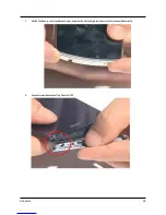
Page 34: ...Chapter 3 28 Replacing the Deco Top Deco Down 1 Putpowerbutton onTop Deco 2 Assemble two sideshooksofTop Deco to S500 ...

Page 35: ...Chapter 3 29 3 SettheTop Deco to correctpositionand press powerbuttonclick feelingto testifpowerbuttonisassembledcorrectly 4 Assemble two sideshooksofTop Deco to S500 ...

Page 36: ...Chapter 3 30 5 SettheTop Deco to correctposition ...

Page 37: ...spare part MB 5 Flash correct OS S500 Service Tool 1 S500 Service Tool provides users with functions as following Read Cloud UUID Read Write 22 characters Code SN Read IMEI Accelerometer and Gyro sensor calibration Light sensor calibration Proximity sensor calibration Get SIM Lock key Activate Deactivate SIM Lock Set SIM Lock data 2 Required Microsoft NET Framework 2 0 is required A9 device driver...

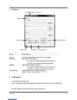
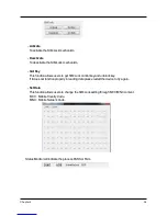
Page 38: ...bug bridge port status The gray icon indicates that device was not found The black icon indicates that device was found Status Monitor It will indicate the running status of process 4 Getting started Launch theAcer Servide Tool Turn on the S500 enable USB debugging mode and connect to computer via USB cable Press the button to perform the function that you want to do Reboot Application NameandVers...

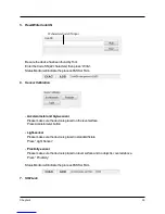
Page 39: ...rometer and Gyro sensor Please make sure the device is placed on the level surface PressAccelerometer button Light sensor Please make sure the device is placed in standard fixture Press Light Sensor Proximity sensor Please make sure the device is placed on level surface and no object is covered above Press Proximity Status Monitor will indicate the process PASS or FAIL 7 SIM Lock 22 characters Cod...

Page 40: ...ws users to get SIM Lock control key and unblock key If it does not function properly in reading data please restart the device to try again Set Data This function allows users to change the SIM Lock setting through MCC MNC content MCC Mobile Country Code MNC Mobile Network Code Status Monitor will indicate the process PASS or FAIL ...

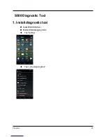
Page 41: ...Chapter 4 35 S500 Diagnostic Tool 1 Install diagnostic tool Install S500 USB driver Enable USB debugging mode Tap Setting Tap Developer options ...

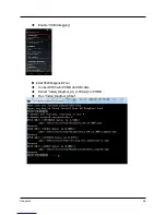
Page 42: ...Chapter 4 36 Enable USB debugging Install S500 Diagnostic Tool Connect S500 witn PC NB via USB cable Extract Install_DiagTool_A9_v1 009 zip on PC NB Run Install_DiagTool_A9 bat ...

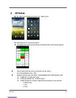
Page 43: ...items show red background Project name and version show on the above of main screen For example DiagTool_A9_v1 006 DiagTool_A9 log saved on the folder data data Diagnostic Fac files DiagTool_A9 TestResult record the test result TestLog txt TestPos txt record test steps TestResult log show numbers mapping below meanings for every test item 0 Default value 1 Fail 2 Pass ...

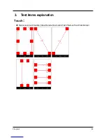
Page 44: ...Chapter 4 38 3 Test items explanation Touch Tests screen touch function follow the red arrow mark to finish 5 items of touch function test ...

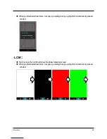
Page 45: ...ool pop up a dialog to let you judge this function test is passed or failed LCM Touch screen then LCM will show the below following screen When you finished all test items tool pop up a dialog to let you judge this function test is passed or failed ...

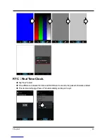
Page 46: ... 40 RTC Real Time Clock Tap Test to start If the difference between first time and third time is 2 seconds it is passed otherwise is failed This item tool will judge Pass or Fail automatically and tap ok to quit ...

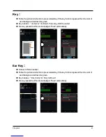
Page 47: ...l Up Vol Down Power key didn t be tested Two key passed test then tool will judge it Pass automatically Ear Key Connect 3 5mm handset Follow the picture s instruction to press related key If the key function is passed then the color of word background will become green Key includes Ear_Vol Up Ear_Vol Down Two key passed test then tool will judge it Pass automatically ...

Page 48: ...hapter 4 42 Vibrator Tap Test then S500 will vibrate three times and you can judge the test is passed or failed SD ExSD Card Insert MicroSD card Tap SD ExSd then tool will show pass or fail automatically ...

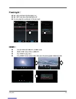
Page 49: ...and check if the flash light is off You can judge the result based on the test result HDMI Connect S500 with HDMI TV via HDMI cable Wait for S500 screen mirror to HDMI TV Tap HDMI to play video If the HDMI TV show correct video and sound the test is passed otherwise is faile ...

Page 50: ...nds per direction Test sequence Z put flat LCM face up Y put plumb LCM face to tester X Turn S500 90 degree clockwise Y Turn S500 90 degree clockwise X Turn S500 90 degree clockwise Z Turn S500 90 degree clockwise and LCM face down Tool judges test pass or fail automatically ...

Page 51: ... S300 Direct S500 toward north the value ofAzimuth is between 0 10 or 350 359 Tap Exam Degree to start Pass Criteria the value of Azimuth changed when move S300 the measured angle should be less than 10 degree 350 359 or 0 10 Tool judges test pass or fail automatically ...

Page 52: ...500 moving it s passed otherwise is failed Tap Back key and selected Yes or No to quit the test Battery InsertAC adapter Tap Test to start Pass Criteria Status Charging or Full Level 0 100 Voltage 3000 4250 Ampere 1200 2000 Temperature 10 70 Tool judges test pass or fail automatically ...

Page 53: ...of Near Far is 0 When your hand move away from p sensor the value of Near Far is 5 Tap Close and selected Yes or No to quit the test L sensor The value of LUX is changed base on the brightness Pass Criteria The light is bright the value of LUX is big The light is dark the value of LUX is small Tap Close and selected Yes or No to quit the test ...

Page 54: ...arphone MIC Tap Test to start Pass Criteria WAV Speaker audio output to speaker WAV Receiver audio output to receiver WAV Earphone audio output to earphone MIC Handset MIC record 5 sec voice from handset MIC then output to speaker MIC Earphone MIC record 5 sec voice from earphone MIC then output to speaker Tap Back key and selected Yes or No to quit the test ...

Page 55: ...availableAP to get RSSI Pass Criteria The RSSI is biger than 69 it s passed otherwise is failed Tool judges test pass or fail automatically GPS You should test GPS function under open sky area Tap Test to start Tool judges test pass or fail automatically ...

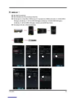
Page 56: ...NFC test NFC Read Mode Check if the battery cover is assembled Tap NFC Read Mode to enable the function Tap Accept to start test Put test card under S500 in 4 cm If S500 read the test card screen show pass Tap Done ...

Page 57: ... to quit the test NFC test NFC Card Mode Check if NFC Test SIM Card inserted Check if the battery cover is assembled Tap NFC Card Mode to enable the function Tap Select SE UICC Tap Get Selected SE Select Card Emulation Tap Active SWP ...

Page 58: ...Chapter 4 52 Put S500 down QP3000 in 4cm and QP3000 will detect S500 to pass this test Tap ExitApplication Close to finish this test ...

Page 59: ...r 4 53 SIM detect SIM card Check SIM Card insert to S500 Tap Test to start Pass Criteria SIM Status Ready Tool judges test pass or fail automatically Camera and Bluetooth use S500 preload application to test ...

Page 60: ...ric yearand week code SSSSS 5 characterunique hexadecimalcode bymanufacturerbaseandreseteachweek 0 9 A B C D E F16code MM Manufacturercode VV English versioncode Code Description YWW 3 digitnumeric yearand week code as above dddddd 6 uniquedecimalnumbersderived fromAcer22 Code SN SSSSS TransferRule S1S2S3S4S5 dddddd S1 16 4 S2 16 3 S3 16 2 S4 16 1 S5 Example AcerFGSN SSSSS 001FD SNID dddddd 1 16 2...

Page 61: ...Chapter 6 55 FRU Field Replaceable Unit List S500 Smartphone Exploded Diagram Chapter 6 ...

Page 62: ... AI H PES04875 A EU AP 0050P 010 PLUG FPK AI H PES04876 A UK AP 0050P 011 PLUG FPC AI H PES05059 A CHINA AP 0050P 024 HEADSET KJAH4028AENCB W QH 00205 007 BATT LI 3 7V BAT 610 1460MAH EN BT 0010S 006 TBD BATT 3 7V BAT 610 A03300402A2 FR KT 0010S 001 TBD BATT 3 7V BAT 610 A03300401A2 CN KT 0010S 002 CABLE MICRO USB B 1M BLK HC 70211 00Q ...

Page 63: ...0511 00H ASSY MB MODULE DC HB 70511 00K ASSY TP MODULE BLACK NOT INCLUDE SPEC LABEL 6M H9WH3 001 TBD ASSY TP MODULE WHITE NOT INCLUDE SPEC LABEL 6M HAQH3 001 VIBRATOR VK328537LW09 3V 60 H9WH3 002 KEYPAD VOLUME GATLB1A 42 H9WH3 001 BTN POWER KEYPAD GATLB1A 42 H9WH3 002 ...

Page 64: ...R WITH NFC WHITE 60 HAQH3 002 TBD ASSY BATTERY COVER WITH NFC for CHINA TBD ASSY A9 DECO TOP 3G 60 H9WH3 004 DECO DOWN ASSY A9 GATLB1A 60 H9WH3 005 ASSY A9 SPEAKER 23 H9WH3 001 ASSY A9 REC XH1206 11 60 H9WH3 006 CAMERA MODULE 11P2BA848 KR 08M05 001 MODULE CAMERA CCFB184 KR 0HD06 001 ...

Page 65: ...07 DEVICE LABEL_EN 47 H9WH3 001 TBD LABEL DEVICE_TW 47 H9WH3 002 TBD LABEL DEVICE_CN 47 H9WH3 003 銀 SCRW T5 M1 6 2 5L 3 5 ZN NYL 86 H9WH3 001 黑 SCRW T5 M1 6 3 5L 3 5 BZN NYL 86 H9WH3 002 LABEL WATER DETECTION 47 H9WH3 004 LABEL SEAL 47 H9WH3 005 ...

Page 66: ...ation section youcan download on allof Acer sproducts including Service guide forallmodels User smanuals Trainingmanuals Software utilities Spare partslists TABs TechnicalAnnouncementBulletin Forthosepurpose we have included anAcrobatFile to facilitate the problem freedownloadingofourtechnicalmaterial Alsocontented on this website are Detailed informationonAcer sInternationalTraveler sWarranty ITW...

Reviews: