10
2.
UNPACKING & MACHINE INSTALLATION
2-1
Unpacking
When the machine has arrived, first, please check to see if the wooden crate
is
damaged or not? Secondly, open the crate and inspect the machine for any damage or shortage
of accessories. If so, please contact our company or insurance company immediately in order
to get the best solution; otherwise our company or the insurance company will not be able to
compensate for the damage.
2-2
Lifting
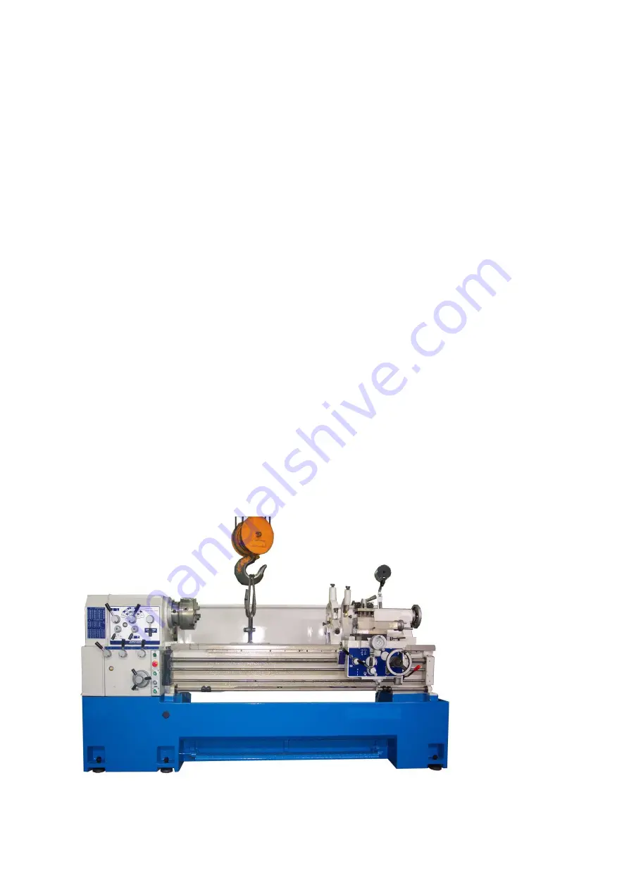
Please refer to figure 2-2 for machine unloading and moving.
The steps for lifting the lathe are:
(1)
Clamp the bedways with a specially made hanger, which consists of a clamp and a wire
rope.
(2)
Raise the lathe a little bit with overhead crane, and then check to see if the lathe is
balanced. If not, please slide hanger’s position left or right to achieve machine’s balance.
(3)
When the machine arrives at the location, slowly put down the machine to the floor.
Please avoid bumps or crash to ensure machine’s accuracy is not altered.
(4)
For easier access to the electrical cabinet, the back side of the lathe or cover of the electric
cabinet should be at least 600mm (2 feet) from wall.
Fig. 2-2
Summary of Contents for Dynamic 1722S
Page 6: ...6 ...
Page 7: ...7 ...
Page 15: ...15 ...
Page 16: ...16 ...
Page 30: ...30 0 27 MD2 0 82 PD10 0 12 MD2 ...
Page 36: ...36 6 4 Lubrication Location A Oil input cap B Oil drain hole ...
Page 43: ...43 ...
Page 44: ...44 8 1 Headstock ...
Page 50: ...50 8 2 Gearbox ...
Page 56: ...56 3 Apron ...
Page 62: ...62 8 4 Bed and Base ...
Page 65: ...65 8 5 Break System ...
Page 68: ...68 8 6 Carriage and Crossfeed ...
Page 70: ...70 35 Washer wave type 6210 2 36 Set screw M6xP1 0x10L 1 ...
Page 72: ...72 70 Tool post square export 1 1003512802 1003512606 local 1 1003512704 1003512508 ...
Page 73: ...73 8 7 Tailstock ...
Page 75: ...75 38 Case 1 1122100502 1122100502 1122100502 39 Wiper 1 1122100100 1122100100 1122100100 ...
Page 77: ...77 8 8 Steady Rest ...
Page 79: ...79 8 9 Follow Rest ...
Page 81: ...81 8 10 Coolant System ...


