11
3.
UNPACKING & MACHINE INSTALLATION
3-1 Unpacking & Lifting
When the machine has arrived, first, check if the wooden case is damaged or not,
secondly, open the case and inspect the machine for any damage or short supply of
accessories. If there is, please contact our company or insurance company
immediately in order to get the best solution or claim; otherwise our company or the
insurance company will not be in the position to compensate for the damage.
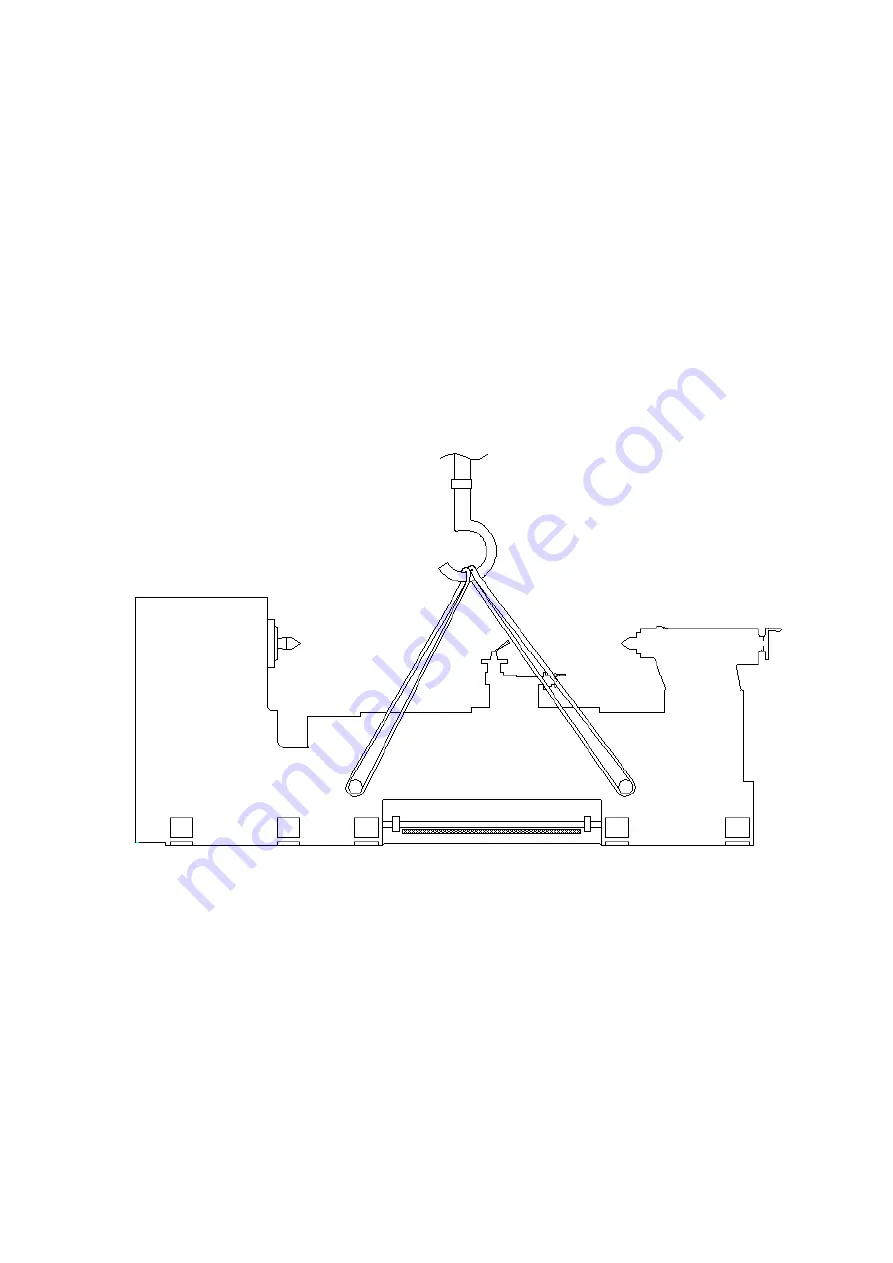
Please refer to below picture for machine unloading from the truck & moving:
The steps for lifting the lathes are:
(1)
Clamp the bed way with a special made hanger and bars (through the base holes),
which consists of a clamp and an iron chain.
(2)
Raise the lathe a little bit with crane, and then check if the lathe is balanced. If
not, move apron and cross slide back or forth to make sure the machine is
balanced.
(3)
While the machine arrives at the location, put down the machine slowly to avoid
any damage of the machine caused by bumps or crash.
(4)
For opening the electrical cabinet, the machine should be located at least 24”
(600mm) from building wall at back side of the electric cabinet.
Summary of Contents for Dynamic 33130
Page 5: ...5 1 Machine Assembly ...
Page 9: ...9 2 4 Circuit Diagram ...
Page 26: ...26 7 Leadscrew Add oil with oil gun As required Once per day 8 Bedways Auto lubrication ...
Page 27: ...27 5 4 Lubrication Location A Oil input hole B Oil drain hole ...
Page 33: ...33 7 1 Headstock Assembly ...
Page 39: ...39 7 2 Gear Box Assembly ...
Page 43: ...43 7 3 Gear Box Cover Assembly ...
Page 45: ...45 7 4 Apron Assembly Right Hand ...
Page 50: ...50 7 4 Apron Assembly Left Hand ...
Page 56: ...56 7 5 Machine Bed and Base Assembly ...
Page 60: ...60 7 6 Brake System ...
Page 63: ...63 7 7 Carriage and Crossfeed System ...
Page 67: ...67 7 8 Tailstock ...
Page 71: ...71 7 9 Chip Guard ...
Page 73: ...73 7 10 Leadscrew Cover and Rear Splash Guard ...


