6
Fig. 1-1
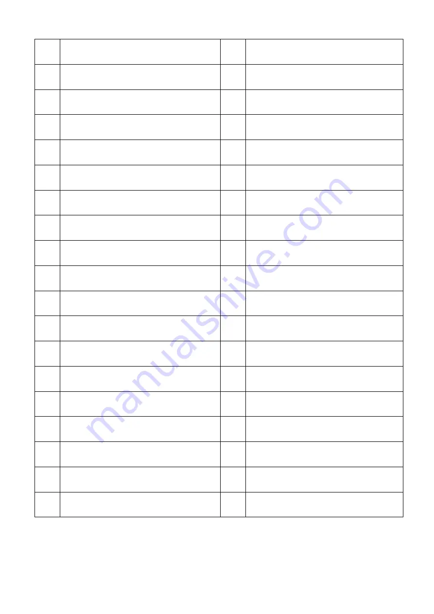
ITEM DESCRIPTION
ITEM DESCRIPTION
1
Forward/Reverse Shifting lever
19 4 steps feed selection dial
2
Spindle speed shifting selection lever
20 Spindle speed W OR M shifting lever
3
Spindle speed H/M/N/L shifting lever
21 Coolant control switch
4
Thread dial indicator
22 Power indicator
5
Cross feeding Handle
23 Main power on/off switch
6
4 way tool post
24 Emergency stop
7
Compound rest
25 Jog button
8
Compound rest handle
26 Half nut engaged lever
9
Tailstock body
27 Longitudinal feed hand wheel
10 Tailstock set over adjusting Screw
28 Auto feeding engaged lever
11 Tailstock body clamping screw
29 Apron hand-wheel
12 Tailstock spindle locking lever
30 Foundation adjusting bolt
13 Spindle speed shifting lever
31 Foot brake pedal
14 Tailstock hand wheel
32 Lead screw
15 Spindle speed A.B shifting lever
33 Auto-feed rod
16 MP & DP thread operate lever
34 Auto feed stop selection rod
17 9 steps feed selection dial
35 Adjustable tripping stop
18 Spindle speed C OR D shifting lever
Summary of Contents for Dynamic 33130
Page 5: ...5 1 Machine Assembly ...
Page 9: ...9 2 4 Circuit Diagram ...
Page 26: ...26 7 Leadscrew Add oil with oil gun As required Once per day 8 Bedways Auto lubrication ...
Page 27: ...27 5 4 Lubrication Location A Oil input hole B Oil drain hole ...
Page 33: ...33 7 1 Headstock Assembly ...
Page 39: ...39 7 2 Gear Box Assembly ...
Page 43: ...43 7 3 Gear Box Cover Assembly ...
Page 45: ...45 7 4 Apron Assembly Right Hand ...
Page 50: ...50 7 4 Apron Assembly Left Hand ...
Page 56: ...56 7 5 Machine Bed and Base Assembly ...
Page 60: ...60 7 6 Brake System ...
Page 63: ...63 7 7 Carriage and Crossfeed System ...
Page 67: ...67 7 8 Tailstock ...
Page 71: ...71 7 9 Chip Guard ...
Page 73: ...73 7 10 Leadscrew Cover and Rear Splash Guard ...


