Chapter 3
71
3.
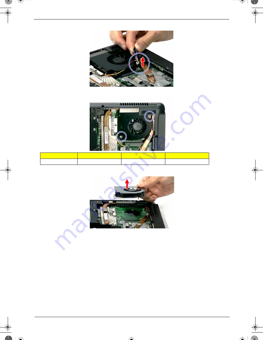
Disconnect the heatsink fan connector from FAN1 on the main board.
4.
Remove the two screws (C) securing the heatsink fan module.
5.
Remove the heatsink fan module from the main board.
Removing the CPU and VGA Heatsink Module
1.
See “Removing the Battery Pack” on page 60.
2.
See “Removing the Lower Cover” on page 62.
Step
Size (Quantity)
Color
Torque
1~2
M2 x L4 (2)
Silver
1.6 kgf-cm
SG_Dallen.book Page 71 Thursday, April 19, 2007 11:08 AM
Summary of Contents for Extensa 5210
Page 6: ...VI SG_Dallen book Page VI Thursday April 19 2007 11 08 AM...
Page 10: ...X Table of Contents SG_Dallen book Page X Thursday April 19 2007 11 08 AM...
Page 14: ...4 Chapter 1 System Block Diagram SG_Dallen book Page 4 Thursday April 19 2007 11 08 AM...
Page 65: ...Chapter 2 55 SG_Dallen book Page 55 Thursday April 19 2007 11 08 AM...
Page 66: ...56 Chapter 2 SG_Dallen book Page 56 Thursday April 19 2007 11 08 AM...
Page 147: ...Chapter 6 137 SG_Dallen book Page 137 Thursday April 19 2007 11 08 AM...
Page 178: ...168 Appendix B SG_Dallen book Page 168 Thursday April 19 2007 11 08 AM...
Page 180: ...170 Appendix C SG_Dallen book Page 170 Thursday April 19 2007 11 08 AM...


