3-4
Service Guide
3.3
Basic System Configuration
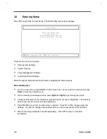
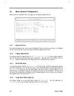
Basic System Configuration has a one-page screen display illustrated below.
Basic System Settings
Date ----------------------- [Dec 06,1996]
Time ----------------------- [10:00:00]
Floppy Disk A -------------- [1.44 MB 3.5-inch]
Floppy Disk B -------------- [ None ]
Cylinder Head Sector
Hard Disk (1160 MB) -------- [Auto] 787 32 63
Large Hard Disk Capacity --- [Enabled]
Memory Test ---------------- [Disabled]
Boot Display --------------- [Auto]
Quiet Boot ----------------- [Enabled]
↑↓
=Move Highlight Bar,
→←
=Change Setting, F1=Help, Esc=Exit
3.3.1
Date and Time
The notebook displays the current date in MM/DD/YY format and the current time in HH:MM:SS
format. It uses a 24-hour clock; for example, 6:25 PM displays as 18:25:00.
3.3.2
Floppy Disk Drives
The default setting for Diskette Drive A is
[1.44 MB 3.5-inch]
and this setting applies to
both an internal and external floppy drive configuration. Diskette Drive B, by default, is set to
[None]
. Enable this parameter if two floppy drives are connected to the notebook.
3.3.3
Hard Disk Drive
The default setting for IDE Drive 0 is
[Auto]
. With this setting, the BIOS automatically detects
your drive parameters. You can also opt to key in your drive parameters by setting this parameter
to
[User]
. To determine your drive parameters, look at the data on the label pasted on your
hard disk drive (or supplied in vendor documentation) and type in the parameters. Be sure to set
the correct drive parameters; otherwise an error message appears when you boot up the notebook.
We suggest you set this parameter to
[Auto]
.
3.3.4
Large Hard Disk Capacity
The default setting for Large Hard Disk Capacity is
[Enabled]
. Set this parameter to
[Disabled]
if you use the UNIX operating system on this computer.
Summary of Contents for Extensa 61X
Page 6: ...vi ...
Page 26: ...1 8 Service Guide Figure 1 5 Main Board Layout Bottom Side ...
Page 49: ...System Introduction 1 31 1 5 1 3 Power Management Figure 1 14 Power Management Block Diagram ...
Page 55: ...System Introduction 1 37 1 6 System Block Diagram Figure 1 15 System Block Diagram ...
Page 64: ...Major Chips Description 2 7 2 2 5 Pin Diagram Figure 2 4 M1521 Pin Diagram ...
Page 99: ...2 42 Service Guide 2 5 3 Pin Diagram Figure 2 10 C T 65550 Pin Diagram ...
Page 117: ...2 60 Service Guide Figure 2 12 Functional block diagram CardBus Card Interface ...
Page 119: ...2 62 Service Guide Figure 2 14 PCI to CardBus terminal assignments ...
Page 135: ...2 78 Service Guide 2 7 3 Pin Diagram Figure 2 16 NS87336VJG Pin Diagram ...
Page 145: ...2 88 Service Guide 2 8 2 Pin Diagram Figure 2 17 YMF715 Block Diagram ...
Page 185: ...Disassembly and Unit Replacement 4 5 Figure 4 3 Disassembly Sequence Flowchart ...
Page 209: ...B 2 Service Guide ...
Page 210: ...Exploded View Diagram B 3 ...

