xviii
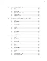
NS87336VJG Pin Descriptions .......................................................................................2-79
YMF715 Descriptions.....................................................................................................2-89
T62.062.C Absolute Maximum Ratings Table ................................................................2-92
T62.062.C Electrical Characteristics Table .....................................................................2-92
T62.062.C Pin Description table .....................................................................................2-95
T62.061.C Pin Descriptions............................................................................................2-98
MAXIMUM RATINGS................................................................................................2-102
Electrical Characteristics ..............................................................................................2-102
Pin Description.............................................................................................................2-103
Pin Description.............................................................................................................2-103
MAXIMUM RATINGS................................................................................................2-105
Electrical Characteristics ..............................................................................................2-105
J1: 52103-1217 (MOLEX) Pin Description..................................................................2-106
J2:SM02(8.0)B-BHS-1-TB2P (JST) Pin Description .....................................................2-106
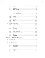
Display Device Settings ....................................................................................................3-5
Floppy Disk Drive Control Settings ..................................................................................3-6
Hard Disk Drive Control Settings .....................................................................................3-6
System Boot Drive Control Settings..................................................................................3-7
CD-ROM Image Descriptions...........................................................................................3-7
System Status Descriptions .............................................................................................3-15
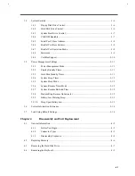
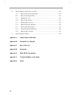
Guide to Disassembly Sequence........................................................................................4-4
Spare Parts List ............................................................................................................... C-1
POST Checkpoint List ..................................................................................................... E-1
Summary of Contents for Extensa 61X
Page 6: ...vi ...
Page 26: ...1 8 Service Guide Figure 1 5 Main Board Layout Bottom Side ...
Page 49: ...System Introduction 1 31 1 5 1 3 Power Management Figure 1 14 Power Management Block Diagram ...
Page 55: ...System Introduction 1 37 1 6 System Block Diagram Figure 1 15 System Block Diagram ...
Page 64: ...Major Chips Description 2 7 2 2 5 Pin Diagram Figure 2 4 M1521 Pin Diagram ...
Page 99: ...2 42 Service Guide 2 5 3 Pin Diagram Figure 2 10 C T 65550 Pin Diagram ...
Page 117: ...2 60 Service Guide Figure 2 12 Functional block diagram CardBus Card Interface ...
Page 119: ...2 62 Service Guide Figure 2 14 PCI to CardBus terminal assignments ...
Page 135: ...2 78 Service Guide 2 7 3 Pin Diagram Figure 2 16 NS87336VJG Pin Diagram ...
Page 145: ...2 88 Service Guide 2 8 2 Pin Diagram Figure 2 17 YMF715 Block Diagram ...
Page 185: ...Disassembly and Unit Replacement 4 5 Figure 4 3 Disassembly Sequence Flowchart ...
Page 209: ...B 2 Service Guide ...
Page 210: ...Exploded View Diagram B 3 ...

