4-4
Service Guide
4.1.3
Disassembly Sequence
The disassembly procedure described in this manual is divided into four major sections:
•
Section 4.2:
Replacing Memory
•
Section 4.3:
Removing the hard disk drive
•
Section 4.4:
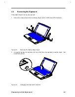
Removing the keyboard
•
Section 4.5:
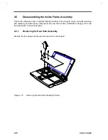
Disassembling the inside frame assembly
•
Section 4.6:
Disassembling the display
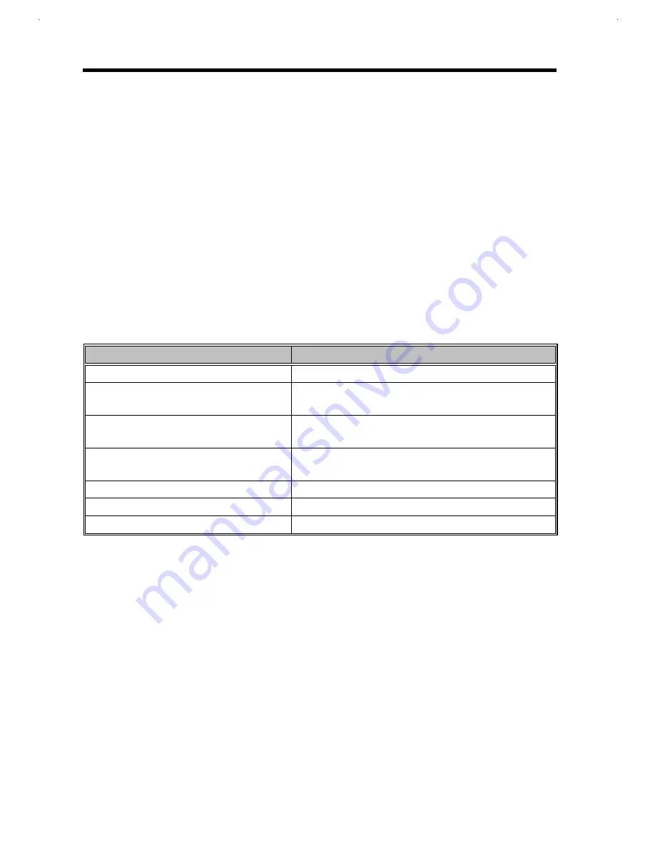
The following table lists the components that need to be removed during servicing. For example,
if you want to remove the motherboard, you must first remove the keyboard, then disassemble the
inside assembly frame in that order.
Table 4-1
Guide to Disassembly Sequence
Service Item
Prerequisite
Remove or replace the hard disk drive
1. Remove HDD Door.
Remove or replace the internal module
1.
Remove the keyboard.
2.
Disassemble the housing
Remove the motherboard for service or
replacement
1.
Remove the keyboard.
2.
Disassemble the housing.
Remove the touchpad
1.
Remove the keyboard
2.
Disassemble the housing
Replace the LCD
Remove the display
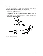
Install CPU
Remove the keyboard (and heat sink assembly)
Install additional memory
Remove DIMM cover
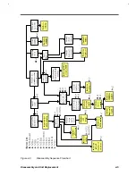
The flowchart on the succeeding page gives a clearer and more graphic representation on the
entire disassembly sequence. Please refer to it from time to time.
Summary of Contents for Extensa 61X
Page 6: ...vi ...
Page 26: ...1 8 Service Guide Figure 1 5 Main Board Layout Bottom Side ...
Page 49: ...System Introduction 1 31 1 5 1 3 Power Management Figure 1 14 Power Management Block Diagram ...
Page 55: ...System Introduction 1 37 1 6 System Block Diagram Figure 1 15 System Block Diagram ...
Page 64: ...Major Chips Description 2 7 2 2 5 Pin Diagram Figure 2 4 M1521 Pin Diagram ...
Page 99: ...2 42 Service Guide 2 5 3 Pin Diagram Figure 2 10 C T 65550 Pin Diagram ...
Page 117: ...2 60 Service Guide Figure 2 12 Functional block diagram CardBus Card Interface ...
Page 119: ...2 62 Service Guide Figure 2 14 PCI to CardBus terminal assignments ...
Page 135: ...2 78 Service Guide 2 7 3 Pin Diagram Figure 2 16 NS87336VJG Pin Diagram ...
Page 145: ...2 88 Service Guide 2 8 2 Pin Diagram Figure 2 17 YMF715 Block Diagram ...
Page 185: ...Disassembly and Unit Replacement 4 5 Figure 4 3 Disassembly Sequence Flowchart ...
Page 209: ...B 2 Service Guide ...
Page 210: ...Exploded View Diagram B 3 ...

