4-12
Service Guide
4.5.3
Replacing the CPU
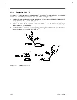
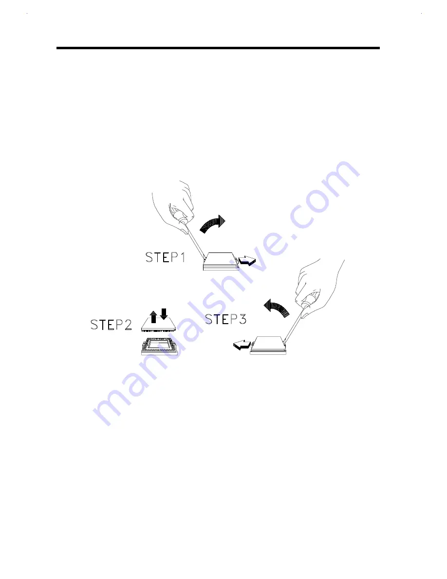
The unique ZIF (zero insertion force) socket allows you to easily remove the CPU. Follow these
steps to remove the CPU and install a replacement CPU. See figure below.
1.
Insert a flat-blade screwdriver into the opening at the left end of the socket (labeled OPEN)
and push towards the other end of the socket.
2.
Pull out the CPU. Then insert the replacement CPU. Insure the CPU is properly keyed
before pressing it into the socket.
3.
Insert a flat-blade screwdriver into the opening at the right end of the socket (labeled LOCK)
and push towards the other end of the socket.
Old CPU
New CPU
Figure 4-12
Replacing the CPU
Summary of Contents for Extensa 61X
Page 6: ...vi ...
Page 26: ...1 8 Service Guide Figure 1 5 Main Board Layout Bottom Side ...
Page 49: ...System Introduction 1 31 1 5 1 3 Power Management Figure 1 14 Power Management Block Diagram ...
Page 55: ...System Introduction 1 37 1 6 System Block Diagram Figure 1 15 System Block Diagram ...
Page 64: ...Major Chips Description 2 7 2 2 5 Pin Diagram Figure 2 4 M1521 Pin Diagram ...
Page 99: ...2 42 Service Guide 2 5 3 Pin Diagram Figure 2 10 C T 65550 Pin Diagram ...
Page 117: ...2 60 Service Guide Figure 2 12 Functional block diagram CardBus Card Interface ...
Page 119: ...2 62 Service Guide Figure 2 14 PCI to CardBus terminal assignments ...
Page 135: ...2 78 Service Guide 2 7 3 Pin Diagram Figure 2 16 NS87336VJG Pin Diagram ...
Page 145: ...2 88 Service Guide 2 8 2 Pin Diagram Figure 2 17 YMF715 Block Diagram ...
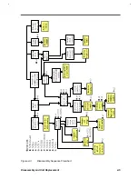
Page 185: ...Disassembly and Unit Replacement 4 5 Figure 4 3 Disassembly Sequence Flowchart ...
Page 209: ...B 2 Service Guide ...
Page 210: ...Exploded View Diagram B 3 ...


