C-
6
Service Guide
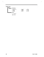
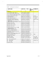
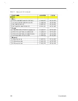
Table C1 Spare parts list (continued)
PART NAME
ACER P/N
TI P/N
options
Misc.
EXT BTY CHARGER 91.48428.001 370P ONLY
91.48428.001
9811764-0001
EXT FLOPPY DRIVE 91.46905.002 370/370P
91.46905.002
9811765-0001
PS/2 CABLE 50.46812.001
50.46812.001
9811766-0001
FILE TRANSFER CABLE 50.30014.001
50.30014.001
9811767-0001
Power
AC ADAPTER ASSY,EXTENSA 61X w/power cord
91.48428.011
9811754-0001
BATTERY PACK,EXTENSA 61X,NIMH SANYO
91.46928.012
9811738-0001
BATTERY PACK,EXTENSA 61X,NIMH TOSHIBA
91.46928.007
9811738-0003
LI-ION 91.46928.003 370/370P, EXT61X
91.46928.003
9811763-0001
Memory
8 MB memory modules
91.46910.001
9811344-0001
16 MB memory modules
91.46910.002
9811344-0002
32 MB memory modules
91.46910.003
9811344-0003
Summary of Contents for Extensa 61X
Page 6: ...vi ...
Page 26: ...1 8 Service Guide Figure 1 5 Main Board Layout Bottom Side ...
Page 49: ...System Introduction 1 31 1 5 1 3 Power Management Figure 1 14 Power Management Block Diagram ...
Page 55: ...System Introduction 1 37 1 6 System Block Diagram Figure 1 15 System Block Diagram ...
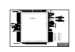
Page 64: ...Major Chips Description 2 7 2 2 5 Pin Diagram Figure 2 4 M1521 Pin Diagram ...
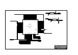
Page 99: ...2 42 Service Guide 2 5 3 Pin Diagram Figure 2 10 C T 65550 Pin Diagram ...
Page 117: ...2 60 Service Guide Figure 2 12 Functional block diagram CardBus Card Interface ...
Page 119: ...2 62 Service Guide Figure 2 14 PCI to CardBus terminal assignments ...
Page 135: ...2 78 Service Guide 2 7 3 Pin Diagram Figure 2 16 NS87336VJG Pin Diagram ...
Page 145: ...2 88 Service Guide 2 8 2 Pin Diagram Figure 2 17 YMF715 Block Diagram ...
Page 185: ...Disassembly and Unit Replacement 4 5 Figure 4 3 Disassembly Sequence Flowchart ...
Page 209: ...B 2 Service Guide ...
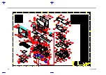
Page 210: ...Exploded View Diagram B 3 ...

