Date:
February 12, 1997
Sheet
16
of
25
Size
Document Number
REV
A3
96149
SC
Title
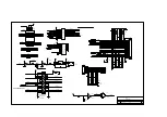
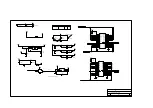
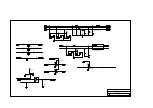
370P/J (AUDIO AMP & CONN)
TAIPEI TAIWAN R.O.C
ACER
12
13
11
1
4
7
U25D
SSHC00
BBT_QCHG
CHARGELED
BBT_QCHG
5VSB_DC
19
5VSB_DC
1
2
3
1
4
7
U25A
SSHC00
9
10
8
1
4
7
U25C
SSHC00
4
5
6
1
4
7
U25B
SSHC00
1
2
R7
47KR3
BT_QCHG
LED#
LED#
5VSB_DC
5VSB_DC
5VSB_DC
5VSB_DC
8
23
3
1
2
QX1
RN1424
1
2
RX2
47KR3
## CIRCUIT MODIFY
13
12
1
4
7
U38F
SSHC14
1
2
R25
22KR3
DISPLED#
DISPLED
+5V
+5V
8
C182
SCD1U
CX36
SC1U16V5JX
+5V
AMPVCC
1
2
L16
MLB321611
SOUND_L
ENAUDIO
C169
SC1U25V5MY
IN-
4
IN+
3
BYPASS
2
SHUTDOWN
1
V
D
D
6
VO1
5
VO2
8
G
N
D
7
U4
LM4861
1
2
R24
22KR3
LINE_OUT_L
SPEAKERLB
AMPVCC
1
2
C179
ST100U10VDK
CX37
SCD1U
1
2
RX13
2K2R3
C5
SC100P
1
2
R6
47KR3
C178, C179 P/N:80.10711.141
1
2
G4
GAP-CLOSE
LINE_OUT_L
SPKR_L
BATPRLED#
CHARGELED
3.3V
14
1
2
3
4
5
6
7
8
9
10
11
12
13
14
15
16
17
18
19
20
CN12
SCON20-2
1
2
D8
S1N4148
CLLED#
SLLED#
NLLED#
SLED
MEDIA_LED#
DISPLED
8
10
10
10
MIC_IN_C
LINE_IN_L
LINE_IN_R
LINE_OUT_R
SPKR_R
15
15
15
LINE_OUT_R
SPEAKERRB
CX35
SCD1U
1
2
RX12
2K2R3
1
2
C178
ST100U10VDK
CX32
SCD1U
C28
SC100P
1
2
R26
47KR3
SOUND_R
CX34
SC1U25V5MY
IN-
4
IN+
3
BYPASS
2
SHUTDOWN
1
V
D
D
6
VO1
5
VO2
8
G
N
D
7
UX4
LM4861
1
2
R5
22KR3
4
5
6
1
4
7
U44B
SSHCT32
9
10
8
1
4
7
U44C
SSHCT32
SPKR_OFF
PCMSPK
SPKR
+5V
+5V
4
8
21
1
2
RX1
47KR3
+5V
## ADD RX1
C252
SC22P
3
1
2
Q7
SMPSA13
1
2
D11
S1N4148
1
2
D10
S1N4148
1
2
R217
47KR3
C253
SCD1U
C254
SCD1U
1
2
R213
33R3
+5V
+5V
1
2
CN10
CON2-10
1
2
CN7
CON2-10
1
2
BZ1
BUZZER-3
4
5
6
1
4
7
U5B
SSHCT32
6377_BIU#
DISABLELED
SPKR_L
SPKR_R
LED#
+5V
23
8
SPEAKERLB
SPEAKERRB
1
2
3
1
4
7
U5A
SSHCT32
BATPRLED#
+5V
Summary of Contents for Extensa 61X
Page 6: ...vi ...
Page 26: ...1 8 Service Guide Figure 1 5 Main Board Layout Bottom Side ...
Page 49: ...System Introduction 1 31 1 5 1 3 Power Management Figure 1 14 Power Management Block Diagram ...
Page 55: ...System Introduction 1 37 1 6 System Block Diagram Figure 1 15 System Block Diagram ...
Page 64: ...Major Chips Description 2 7 2 2 5 Pin Diagram Figure 2 4 M1521 Pin Diagram ...
Page 99: ...2 42 Service Guide 2 5 3 Pin Diagram Figure 2 10 C T 65550 Pin Diagram ...
Page 117: ...2 60 Service Guide Figure 2 12 Functional block diagram CardBus Card Interface ...
Page 119: ...2 62 Service Guide Figure 2 14 PCI to CardBus terminal assignments ...
Page 135: ...2 78 Service Guide 2 7 3 Pin Diagram Figure 2 16 NS87336VJG Pin Diagram ...
Page 145: ...2 88 Service Guide 2 8 2 Pin Diagram Figure 2 17 YMF715 Block Diagram ...
Page 185: ...Disassembly and Unit Replacement 4 5 Figure 4 3 Disassembly Sequence Flowchart ...
Page 209: ...B 2 Service Guide ...
Page 210: ...Exploded View Diagram B 3 ...

