1-
38
Service Guide
1.7
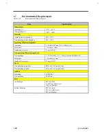
Environmental Requirements
Table 1-42
Environmental Requirements
Item
Specification
Temperature
Operating (ºC)
+5
°
C ~ +35
°
C
Non-operating(ºC)
-20
°
C ~ +60
°
C
Humidity
Operating (non-condensing)
20% ~ 80%
Non-operating (non-condensing)
20% ~ 80%
Operating Vibration (unpacked)
Operating
5 - 25.6Hz, 0.38mm; 25.6 - 250Hz, 0.5G
Sweep rate
> 1 minute / octave
Number of test cycles
2 / axis (X,Y,Z)
Non-operating Vibration (unpacked)
Non-operating
5 - 27.1Hz, 0.6G; 27.1 - 50Hz, 0.41mm; 50~500Hz, 2G
Sweep rate
> 2 minutes / octave
Number of text cycles
4 / axis (X,Y,Z)
Shock
Non-operating (unpacked)
40G peak, 11±1ms, half-sine
Non-operating (packed)
50G peak, 11±1ms, half-sine
Altitude
Operating
10,000 feet
Non-operating
40,000 feet
ESD
Air discharge
8kV (no error)
12.5kV (no restart error)
15kV (no damage)
Contact discharge
4kV (no error)
6kV (no restart error)
8kV (no damage)
Summary of Contents for Extensa 61X
Page 6: ...vi ...
Page 26: ...1 8 Service Guide Figure 1 5 Main Board Layout Bottom Side ...
Page 49: ...System Introduction 1 31 1 5 1 3 Power Management Figure 1 14 Power Management Block Diagram ...
Page 55: ...System Introduction 1 37 1 6 System Block Diagram Figure 1 15 System Block Diagram ...
Page 64: ...Major Chips Description 2 7 2 2 5 Pin Diagram Figure 2 4 M1521 Pin Diagram ...
Page 99: ...2 42 Service Guide 2 5 3 Pin Diagram Figure 2 10 C T 65550 Pin Diagram ...
Page 117: ...2 60 Service Guide Figure 2 12 Functional block diagram CardBus Card Interface ...
Page 119: ...2 62 Service Guide Figure 2 14 PCI to CardBus terminal assignments ...
Page 135: ...2 78 Service Guide 2 7 3 Pin Diagram Figure 2 16 NS87336VJG Pin Diagram ...
Page 145: ...2 88 Service Guide 2 8 2 Pin Diagram Figure 2 17 YMF715 Block Diagram ...
Page 185: ...Disassembly and Unit Replacement 4 5 Figure 4 3 Disassembly Sequence Flowchart ...
Page 209: ...B 2 Service Guide ...
Page 210: ...Exploded View Diagram B 3 ...


