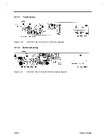
Major Chips Description
2-89
2.8.3
Pin Descriptions
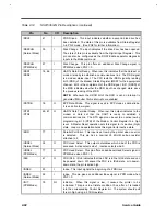
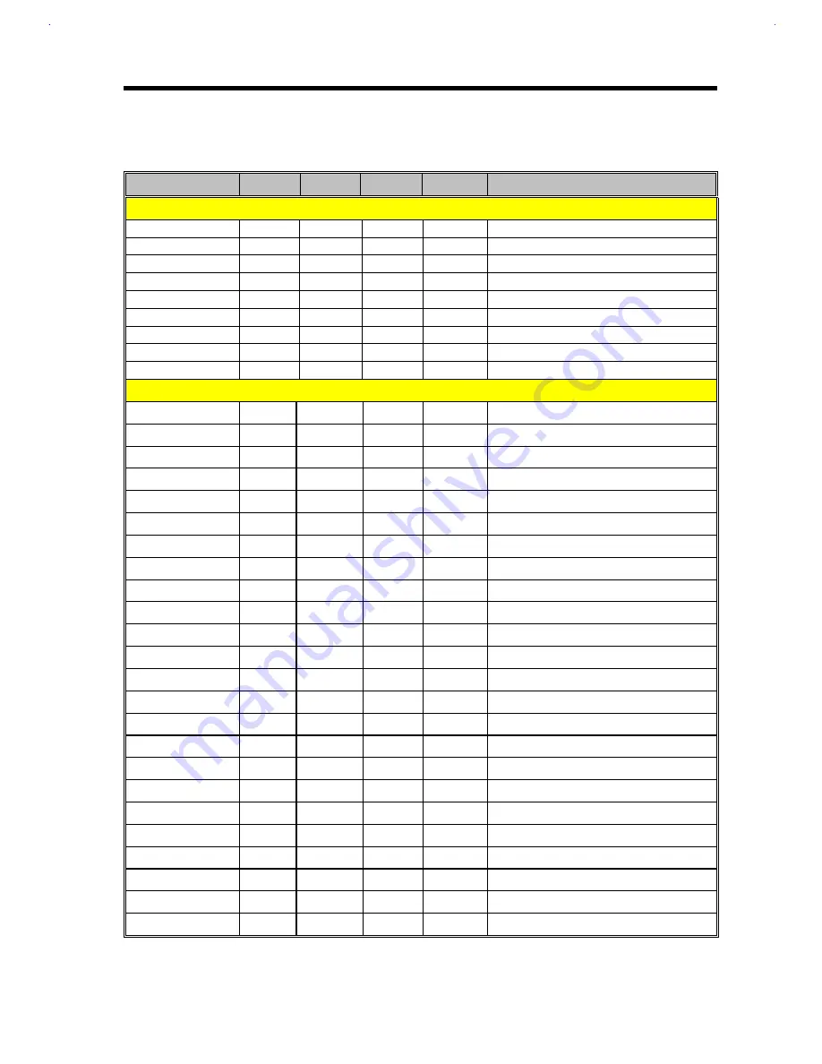
Table 2-15
YMF715 Descriptions
Pin name
Pins
I/O
Type
Size
Function
ISA bus interface: 36 pins
D7-0
8
I/O
TTL
24mA
Data Bus
Al 1-0
12
I
TTL
2mA
Address Bus
AEN
1
I
TTL
2mA
Address Bus Enable
/IOW
1
I
Schmitt
4mA
Write Enable
/IOR
1
I
Schmitt
4mA
Read Enable
RESET
1
I
Schmitt
4mA
Reset
IRQ3,5,7,9,10,11
6
T
TTL
12mA
Interrupt request
DRQ0,1,3
3
T
TTL
12mA
DMA Request
/DACK0, 1,3
3
I
TTL
2mA
DMA Acknowledge
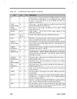
Analog Input & Output : 24 sins
OUTL
1
O
-
-
Left mixed analog output
OUTR
1
O
-
-
Right mixed analog output
VREFI
1
I
-
-
Voltage reference input
VREFO
1
O
-
-
Voltage reference output
AUXIL
l
I
-
-
Left AUX1 input
AUX1R
l
I
-
-
Right AUX1 input
AIJX2L
l
I
-
-
Left AUX2 input
AUX2R
1
I
-
-
Right AUX2 input
LINEL
1
I
-
-
Left LINE input
LINER
1
I
-
-
Right LINE input
MIC
1
I
-
-
MIC input
MIN
1
I
-
-
Monaural input
TRECL
1
-
-
-
Left Treble capacitor
TRECR
1
-
-
-
Right Treble-capacitor
SBFLTL
1
-
-
-
Left SBDAC filter
SBFLTR
1
-
-
-
Right SBDAC filter
SYNSHL
1
-
-
-
Left SYNDAC sample / hold capacitor
SYNSHR
1
-
-
-
Right SYNDAC sample / hold capacitor
ADFLTL
1
-
-
-
Left input filter
ADFLTR
1
-
-
-
Right input filter
VOCOL
1
O
-
-
Left voice output
VOCOR
I
O
-
-
Right voice output
VOCIL
1
I
-
-
Left voice input
VOCIR
1
I
-
-
Right voice input
Summary of Contents for Extensa 61X
Page 6: ...vi ...
Page 26: ...1 8 Service Guide Figure 1 5 Main Board Layout Bottom Side ...
Page 49: ...System Introduction 1 31 1 5 1 3 Power Management Figure 1 14 Power Management Block Diagram ...
Page 55: ...System Introduction 1 37 1 6 System Block Diagram Figure 1 15 System Block Diagram ...
Page 64: ...Major Chips Description 2 7 2 2 5 Pin Diagram Figure 2 4 M1521 Pin Diagram ...
Page 99: ...2 42 Service Guide 2 5 3 Pin Diagram Figure 2 10 C T 65550 Pin Diagram ...
Page 117: ...2 60 Service Guide Figure 2 12 Functional block diagram CardBus Card Interface ...
Page 119: ...2 62 Service Guide Figure 2 14 PCI to CardBus terminal assignments ...
Page 135: ...2 78 Service Guide 2 7 3 Pin Diagram Figure 2 16 NS87336VJG Pin Diagram ...
Page 145: ...2 88 Service Guide 2 8 2 Pin Diagram Figure 2 17 YMF715 Block Diagram ...
Page 185: ...Disassembly and Unit Replacement 4 5 Figure 4 3 Disassembly Sequence Flowchart ...
Page 209: ...B 2 Service Guide ...
Page 210: ...Exploded View Diagram B 3 ...


