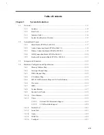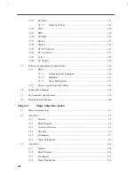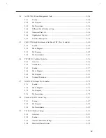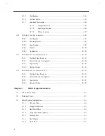
System Introduction
1-
3
1.1.2
Rear Ports
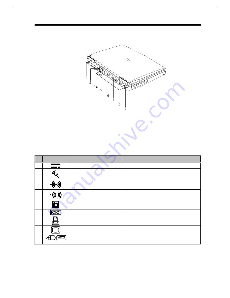
1
DC-in Port
6
Serial Port
2
Microphone-in Port
7
Parallel Port
3
Line-in Port
8
External CRT Port
4
Line-out Port
9
PS/2 Port
5
External Floppy Drive Connector
Figure 1-2
Rear Ports
The following table describes these ports.
Table 1-1
Port Descriptions
#
Icon
Port
Connects to...
1
DC-in Port
AC adapter and power outlet
2
Microphone-in Port
External 3.5mm minijack condenser microphone
3
Line-in Port
Line-in device (e.g., CD player, stereo walkman)
4
Line-out Port
Line-out device (e.g., speakers, headphones)
5
External Floppy Drive Connector
External floppy drive
6
Serial Port
Serial device (e.g., serial mouse)
7
Parallel Port
Parallel device (e.g., parallel printer)
8
External CRT port
Monitor (up to 1024x768, 256-colors )
9
PS/2 Port
PS/2-compatible device
(e.g., PS/2 keyboard, keypad, mouse)
1.1.3
Indicator Light
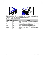
A two-way indicator light is found on the inside and outside of the display. See figure below.
Summary of Contents for Extensa 61X
Page 6: ...vi ...
Page 26: ...1 8 Service Guide Figure 1 5 Main Board Layout Bottom Side ...
Page 49: ...System Introduction 1 31 1 5 1 3 Power Management Figure 1 14 Power Management Block Diagram ...
Page 55: ...System Introduction 1 37 1 6 System Block Diagram Figure 1 15 System Block Diagram ...
Page 64: ...Major Chips Description 2 7 2 2 5 Pin Diagram Figure 2 4 M1521 Pin Diagram ...
Page 99: ...2 42 Service Guide 2 5 3 Pin Diagram Figure 2 10 C T 65550 Pin Diagram ...
Page 117: ...2 60 Service Guide Figure 2 12 Functional block diagram CardBus Card Interface ...
Page 119: ...2 62 Service Guide Figure 2 14 PCI to CardBus terminal assignments ...
Page 135: ...2 78 Service Guide 2 7 3 Pin Diagram Figure 2 16 NS87336VJG Pin Diagram ...
Page 145: ...2 88 Service Guide 2 8 2 Pin Diagram Figure 2 17 YMF715 Block Diagram ...
Page 185: ...Disassembly and Unit Replacement 4 5 Figure 4 3 Disassembly Sequence Flowchart ...
Page 209: ...B 2 Service Guide ...
Page 210: ...Exploded View Diagram B 3 ...

