Installation
2-13
Windows for Workgroups, use the
WinMode Utility
).
5.
Install the correct driver, if required (refer to the Monitor Installation
Instructions supplied by the CRT vendor).
2.5 Primary Battery Pack Installation
1.
Turn off the computer and disconnect the AC adapter if attached to the
computer.
2.
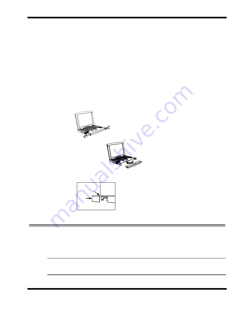
Unlatch the end locks by pushing the endcaps outward with your thumbs.
3.
Align battery connector to connector on notebook and insert the battery pack
into the battery compartment; then push the battery in completely until you
feel the contacts engage.
4.
Relatch the battery locks on both ends of the battery.
Figure 2-10 Notebook Battery Removal/Replacement
2.6 Installing the AC Power Adapter
Use the following procedures to connect the AC adapter to the system:
Caution: Use only the AC adapter supplied with the computer; other
adapters can damage the unit.
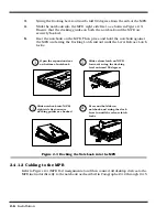
Unlock Battery Pack
Remove Battery
from Front of Notebook
If Battery Lock comes off,
reinstall as shown
Flush
Slide
Summary of Contents for Extensa 900 Series
Page 1: ...Maintenance Manual ExtensaTM 900 Series Notebook Computers 9813715 0001 December 1996 ...
Page 10: ......
Page 28: ......
Page 44: ......
Page 56: ......
Page 82: ......
Page 98: ......
Page 138: ...A 2 Notebook Schematic Diagrams Figure A 1 Notebook Main Board Logic Diagrams Sheet 1 of 30 ...
Page 139: ...Notebook Schematic Diagrams A 3 Figure A 1 Notebook Main Board Logic Diagrams Sheet 2 of 30 ...
Page 140: ...A 4 Notebook Schematic Diagrams Figure A 1 Notebook Main Board Logic Diagrams Sheet 3 of 30 ...
Page 141: ...Notebook Schematic Diagrams A 5 Figure A 1 Notebook Main Board Logic Diagrams Sheet 4 of 30 ...
Page 142: ...A 6 Notebook Schematic Diagrams Figure A 1 Notebook Main Board Logic Diagrams Sheet 5 of 30 ...
Page 143: ...Notebook Schematic Diagrams A 7 Figure A 1 Notebook Main Board Logic Diagrams Sheet 6 of 30 ...
Page 145: ...Notebook Schematic Diagrams A 9 Figure A 1 Notebook Main Board Logic Diagrams Sheet 8 of 30 ...
Page 146: ...A 10 Notebook Schematic Diagrams Figure A 1 Notebook Main Board Logic Diagrams Sheet 9 of 30 ...
Page 147: ...Notebook Schematic Diagrams A 11 Figure A 1 Notebook Main Board Logic Diagrams Sheet 10 of 30 ...
Page 148: ...A 12 Notebook Schematic Diagrams Figure A 1 Motherboard PWB Logic Diagrams Sheet 11 of 23 ...
Page 149: ...Notebook Schematic Diagrams A 13 Figure A 1 Notebook Main Board Logic Diagrams Sheet 12 of 30 ...
Page 153: ...Notebook Schematic Diagrams A 17 Figure A 1 Notebook Main Board Logic Diagrams Sheet 16 of 30 ...
Page 154: ...A 18 Notebook Schematic Diagrams Figure A 1 Notebook Main Board Logic Diagrams Sheet 17 of 30 ...
Page 155: ...Notebook Schematic Diagrams A 19 Figure A 1 Notebook Main Board Logic Diagrams Sheet 18 of 30 ...
Page 156: ...A 20 Notebook Schematic Diagrams Figure A 1 Notebook Main Board Logic Diagrams Sheet 19 of 30 ...
Page 157: ...Notebook Schematic Diagrams A 21 Figure A 1 Notebook Main Board Logic Diagrams Sheet 20 of 30 ...
Page 158: ...A 22 Notebook Schematic Diagrams Figure A 1 Notebook Main Board Logic Diagrams Sheet 21 of 30 ...
Page 159: ...Notebook Schematic Diagrams A 23 Figure A 1 Notebook Main Board Logic Diagrams Sheet 22 of 30 ...
Page 160: ...A 24 Notebook Schematic Diagrams Figure A 1 Notebook Main Board Logic Diagrams Sheet 23 of 30 ...
Page 161: ...Notebook Schematic Diagrams A 25 Figure A 1 Notebook Main Board Logic Diagrams Sheet 24 of 30 ...
Page 166: ...A 30 Notebook Schematic Diagrams Figure A 1 Notebook Main Board Logic Diagrams Sheet 29 of 30 ...
Page 168: ......
Page 171: ...MPB Schematic Diagrams B 3 Figure B 1 MPB CPU Board Logic Diagrams Sheet 2 of 3 ...
Page 176: ...B 8 MPB Schematic Diagrams Figure B 3 MPB Main Board Motherboard Logic Diagrams Sheet 3 of 10 ...
Page 196: ......
Page 197: ......
Page 198: ......


