


Contents
Table of Contents
................................................................................. 3
...................................................................................... 4
2. Wiring connectivity diagram
.................................................................... 5
.............................................................................. 6
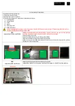
4. Disassembly and Assembly SOP
............................................................ 7
....................................................................................... 12
Safety Notice
Any person attempting to service this chassis must familiarize with the chassis and be aware
of the necessary safety precautions to be used when serving electronic equipment containing
high voltage


