Jumper and Connector Locations
5-3
Jumper and Connector Locations
Mainboard
0
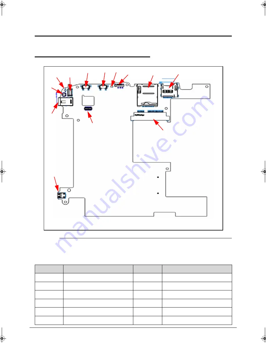
Figure 5-1.
Mainboard Top
Table 5-1.
Mainboard Top
Item
Description
Item
Description
LED3
Power / Battery LED
JP9
Micro SD connector
VB1
Vibrator
JMIN2
3G connector
SW2, SW3
Volume key
SW4
Power button
U135
Light sensor
JLINE1
Audio Jack
SW5
Lock key
JHDMI1
HDMI connector
JP2
SIM connector
JP67
5M camera connector
LED3 VB1
SW2
SW3 U135
SW5
JP2
JP9
JMIN2
SW4
JLINE1
JP67
JHDMI1
SG_PICASSO.book Page 3 Thursday, March 10, 2011 8:08 AM
Summary of Contents for Picasso
Page 1: ...Picasso SERVICE GUIDE ...
Page 9: ...CHAPTER 1 Hardware Specifications ...
Page 11: ...1 3 Card Reader 1 27 System LED Indicator 1 27 System DMA Specification 1 28 ...
Page 12: ...1 4 ...
Page 39: ...CHAPTER 2 System Utilities ...
Page 40: ...2 2 Introduction 2 3 ...
Page 41: ...System Utilities 2 3 System Utilities Introduction 0 ...
Page 42: ...2 4 System Utilities ...
Page 43: ...CHAPTER 3 Maintenance Procedures ...
Page 87: ...Machine Maintenance Procedures 3 45 ID Size Quantity Screw Type A M2 0x4 0 Ni 2 ...
Page 99: ...CHAPTER 4 Troubleshooting ...
Page 118: ...4 20 Troubleshooting ...
Page 119: ...CHAPTER 5 Jumper and Connector Locations ...
Page 120: ...5 2 Mainboard 5 3 ...
Page 123: ...CHAPTER 6 Field Replaceable Unit List ...
Page 124: ...6 2 Exploded Diagrams 6 4 Main Assembly 6 4 FRU List 6 8 Screw List 6 12 ...
Page 135: ...CHAPTER 7 Model Definition and Configuration ...
Page 136: ...7 2 A500 7 3 A501 7 12 ...
Page 160: ...7 26 Model Definition and Configuration ...
Page 161: ...CHAPTER 8 Test Compatible Components ...
Page 162: ...8 2 Android OS Environment Test 8 4 ICONIA Tablet A500 501 8 4 ...
Page 166: ...8 6 Test Compatible Components ...
Page 167: ...CHAPTER 9 Online Support Information ...
Page 168: ...9 2 Introduction 9 3 ...
Page 170: ...9 4 Online Support Information ...


