background image


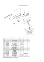
1. 

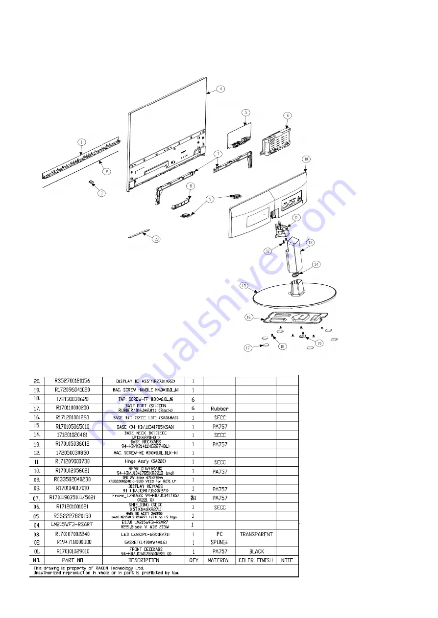
Exploded Diagram 


Summary of Contents for SA220Q

Page 1: ...1 ACER Monitor SA220Q LIFECYCLE EXTENSION GUIDE...

Page 2: ...Mechanical Instructure 6 4 Assembly and Disassembly Procedures 7 5 Troubleshooting 16 6 FRU List 19 Safety Notice Any person attempting to service this chassis must familiarize with the chassis and be...

Page 3: ...repairing method may damage equipment or products It is recommended that service engineers should have repairing knowledge experience as well as appropriate product training per new model before perfo...

Page 4: ...4 1 Exploded Diagram...

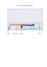
Page 5: ...5 2 Wiring Connectivity diagram...

Page 6: ...and size of the tools that would typically can be used to disassemble the product to a point where components and materials requiring selective treatment can be removed Tool Description working table...

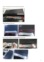
Page 7: ...isassembly Procedures Disassembly Procedure Step 1 Pull the base stand assembly out Step 2 Unscrew two screws at the I O area Step 3 Disassemble rear cover by a thin plastic tool from a slot at the bo...

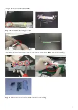
Page 8: ...8 Step 4 Pull up the rear cover and puul out all connectors Step 5 Disassemble deco cover Step 6 Unscrew PCBA s screws and disassemble frame L R...

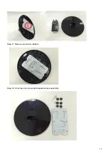
Page 9: ...Remove all cables from LCM Step 8 Remove FFC from display board Step 9 Unscrew hex nuts and six screws and remove main board PCBA from main shielding Step 10 Unscrew the screw and separate base neck...

Page 10: ...10 Step 11 Remove six silicon rubbers Step 12 Unscrew six screws and separate base assembly...

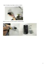
Page 11: ...11 Step 13 Unscrew two screws and remove bracket Step 14 Unscrew two screw and separate HINGE assembly...

Page 12: ...12 Assembly Procedure Step1 Assembly 8 FFC to key board Step2 Assembly key board to rear cover Step3 Assemble deco cover to LCM...

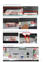
Page 13: ...ep5 Assembly main board into shielding and insert 30pin FFC to MB put main board on LCM Step6 Insert 30 pin LVDS FFC to LCM then use yellow tape to tape FFC Step7 Lock crews to fix MB Step3 Insert 6pi...

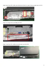
Page 14: ...tep8 Insert 10pin FFC to LCM and LCM and inert 30pin FC to panel then use yellow tape to fix FFC Step9 Use Al taple the tape shielding and LCM Step10 Insert 8pin FFC to MB and assembly rear cover with...

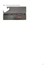
Page 15: ...15 Step11 Lock rear cover screw in red circle...

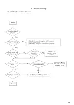
Page 16: ...16 5 Troubleshooting 5 1 Test flow for abnormal machine...

Page 17: ...17 5 2 LED backlight debug flow End...

Page 18: ...18 5 3 Power debug flow...

Page 19: ...5 002 R352700120156 DISPLAY BD ASS Y R271H R2 CABLE 50 T6KM5 001 R046428080860 WH FFC 8P 0 5mm 235mm 1FOLD 60V G F A8 A5 LF CABLE 50 T6KM5 003 R046428100800 WH FFC 10P 0 5mm 320mm 3FOLD PRO 60V G F A8...

Reviews: