Chapter 3
63
1.
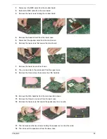
Disconnect the MDC cable from the modem board.
2.
Detach the MDC cable from the main board.
3.
Remove the two screws holding the modem board.
4.
Remove the modem board from the lower case.
5.
Disconnect the speaker cable from the main board.
6.
Remove the two screws that secure the main board.
7.
Remove the two screw nuts as shown.
8.
The you can detach the main board from the upper case.
9.
Remove the three screws that secure the VGA heatsink.
10.
Remove the VGA heatsink from the main board as shown.
11.
Remove the three in one cover from the lower case.
12.
Remove the two screws that secure the speaker set on one side.
13.
Then remove another two screws holding the speaker set on the other side.
14.
Then take out the speaker set from the lower case.
Summary of Contents for Travelmate 2300 Series
Page 6: ...VI ...
Page 15: ...8 Chapter 1 9 Power button Turns the computer on and off ...
Page 43: ...36 Chapter 1 ...
Page 67: ...60 Chapter 3 ...
Page 71: ...64 Chapter 3 ...
Page 75: ...68 Chapter 3 ...
Page 101: ...94 Chapter 5 5 Lid Switch SW2 11 Touchpad Board Connector CN8 6 Modem Cable Connector CN4 ...
Page 105: ...98 Chapter 6 Exploded Diagram ...
Page 121: ...114 Chapter 6 ...
Page 122: ...Chapter 6 115 ...
Page 131: ...126 Appendix C ...

