Chapter 1
1
Chapter 1
System Specifications
1
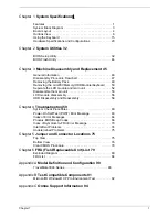
Features . . . . . . . . . . . . . . . . . . . . . . . . . . . . . . . . . . . . . . . . . 1
System Block Diagram . . . . . . . . . . . . . . . . . . . . . . . . . . . . . . 3
Board Layout . . . . . . . . . . . . . . . . . . . . . . . . . . . . . . . . . . . . . 4
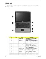
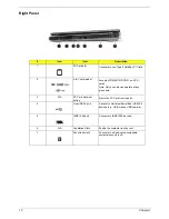
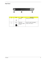
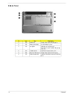
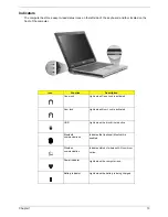
Outlook View . . . . . . . . . . . . . . . . . . . . . . . . . . . . . . . . . . . . . . 6
Using the Keyboard . . . . . . . . . . . . . . . . . . . . . . . . . . . . . . . 15
Hardware Specifications and Configurations . . . . . . . . . . . . 23
Chapter 2
System Utilities 32
BIOS Setup Utility . . . . . . . . . . . . . . . . . . . . . . . . . . . . . . . . . 32
BIOS Flash Utility . . . . . . . . . . . . . . . . . . . . . . . . . . . . . . . . . 44
Chapter 3
Machine Disassembly and Replacement 45
General Information . . . . . . . . . . . . . . . . . . . . . . . . . . . . . . . . 46
Disassembly Procedure Flowchart . . . . . . . . . . . . . . . . . . . . 47
Removing the Battery Pack . . . . . . . . . . . . . . . . . . . . . . . . . 49
Removing the miniPCI/Memory/HDD Module/Keyboard . . . 50
Seperate the LCD module and main unit . . . . . . . . . . . . . . . 52
Disassemble the main unit . . . . . . . . . . . . . . . . . . . . . . . . . . 53
LCD module disassembly . . . . . . . . . . . . . . . . . . . . . . . . . . . 56
HDD Disassembly and Reassembly . . . . . . . . . . . . . . . . . . . 58
Chapter 4
Troubleshooting 59
System Check Procedures . . . . . . . . . . . . . . . . . . . . . . . . . . 60
Power-On Self-Test (POST) Error Message . . . . . . . . . . . . 63
Index of Error Messages . . . . . . . . . . . . . . . . . . . . . . . . . . . . 64
Phoenix BIOS Beep Codes . . . . . . . . . . . . . . . . . . . . . . . . . 66
Index of Symptom-to-FRU Error Message . . . . . . . . . . . . . . 70
Intermittent Problems . . . . . . . . . . . . . . . . . . . . . . . . . . . . . . 74
Undetermined Problems . . . . . . . . . . . . . . . . . . . . . . . . . . . . 75
Chapter 5
Jumper and Connector Locations 75
Top View . . . . . . . . . . . . . . . . . . . . . . . . . . . . . . . . . . . . . . . . 75
Bottom View . . . . . . . . . . . . . . . . . . . . . . . . . . . . . . . . . . . . . 76
Clear CMOS Procedure. . . . . . . . . . . . . . . . . . . . . . . . . . . . . 78
Chapter 6
FRU (Field Replaceable Unit) List 79
Exploded Diagram . . . . . . . . . . . . . . . . . . . . . . . . . . . . . . . . 80
FRU List . . . . . . . . . . . . . . . . . . . . . . . . . . . . . . . . . . . . . . . . 84
Appendix A
Model Definition and Configuration 90
TravelMate 3000 Series . . . . . . . . . . . . . . . . . . . . . . . . . . . 90
Appendix B
Test Compatible Components 91
Microsoft® Windows® XP Pro Environment Test . . . . . . . . . 92
Appendix C
Online Support Information 94
Summary of Contents for TravelMate 3000
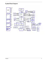
Page 9: ...Chapter 1 3 System Block Diagram ...
Page 10: ...4 Chapter 1 Board Layout Top View Bottom View ...
Page 56: ...50 Chapter 3 6 Remove the keyboard from the main unit ...
Page 81: ...Chapter 5 75 Top View Jumper and Connector Locations Chapter 5 ...
Page 82: ...76 Chapter 5 Bottom View ...
Page 89: ...Chapter 6 83 11 LCD rubber Down 2 12 Screw M2 0 4 0 I NI NYLOK 4 Item Description Q ty ...
Page 101: ...95 Appendix C ...

