24
Chapter 1
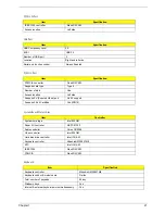
Power Management
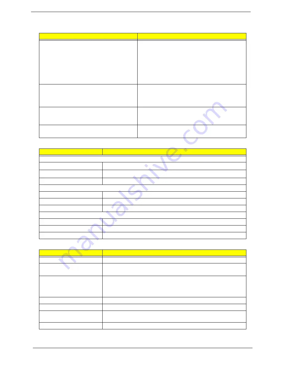
Power Saving Mode
Phenomenon
Standby Mode
Waiting time specified by the System Standby value
or the operating system elapses without any system
activity.
Or
When the computer is about to enter Hibernation
mode (e.g. during a battery-low condition), but the
Hibernation file is invalid or not present.
The Sleep indicator lights up
Hibernation Mode
When customized functions for power management
are set to Hibernation and the corresponding action is
taken.
All power shuts off
Display Standby Mode
Keyboard, built-in touchpad, and an external PS/2
pointing device are idle for a specified period.
The display shuts off
Hard Disk Standby Mode
Hard disk is idle within a specified period of time
Hard disk drive is in standby mode. (spindle turned-off)
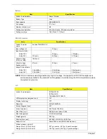
Environmental Requirements
Item
Specification
Temperature
Operating
5 ~ +35
°
C
Non-operating
-20 ~ +65
°
C (unpacked)
Non-operating
Non (storage package)
Humidity
Operating
20% to 80% RH, non-condensing
Non-operating
20% to 80% RH, non-condensing (unpacked)
Non-operating
Non (storage package)
Vibration
Operating (unpacked)
5 ~ 500Hz: 1.0Grms (random)
Non-operating (unpacked)
5 ~ 500Hz: 2.16Grms (random)
Non-operating (packed)
5 ~ 500Hz: 2.16Grms (random)
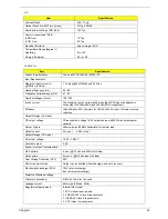
Mechanical Specification
Item
Specification
Dimensions
273mm (W) x 231mm (D) x 24mm (H) (10.76 x 9.10 x 0.95 inches)
Weight
1.70Kg (3.7 lbs) with 6-cell battery
1.55Kg (3.4 lbs) with 4-cell battery
I/O Ports
Two USB port, one VGA (external monitor) port, Microphone/line-in jack,
Headphone/external speakers/line-out jack, RJ-11 port for modem, RJ-45 port
for Ethernet, one PCMCIA (Type II) slot, DC-in jack for AC adapter, one
IEEE1394 port, infrared port, 3-in 1 card reader for memory cards
Drive Bays
One
Material
Plastic, aluminum-magnesium alloy
Indicators
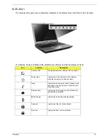
Wireless LAN enable/disable LED, Power/Suspend Mode LED, Sleep LED,
Media activity LED, Battery Charge LED, Caps Lock LED, Num Lock LED
Switch
Power
Summary of Contents for TravelMate 370 series
Page 6: ...VI ...
Page 10: ...2 Chapter 1 System Block Diagram ...
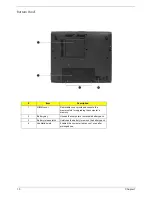
Page 12: ...4 Chapter 1 Bottom View 1 South Bridge 3 DIMM Slot 2 DIMM Slot 4 USB port 1 2 3 4 ...
Page 50: ...42 Chapter 3 ...
Page 51: ...Chapter 3 43 Removing the Battery 1 Slide the two battery latches 2 Then remove the battery ...
Page 76: ...68 Chapter 4 ...
Page 78: ...70 Chapter 5 Bottom View 1 South Bridge 3 DIMM Slot 2 DIMM Slot 4 USB port 1 2 3 4 ...
Page 92: ...84 Appendix B ...
Page 94: ...86 Appendix C ...
Page 95: ...www s manuals com ...

