Chapter 2
31
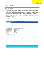
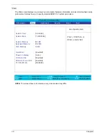
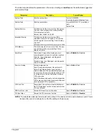
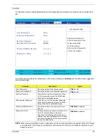
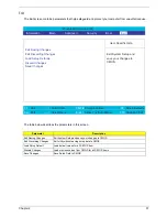
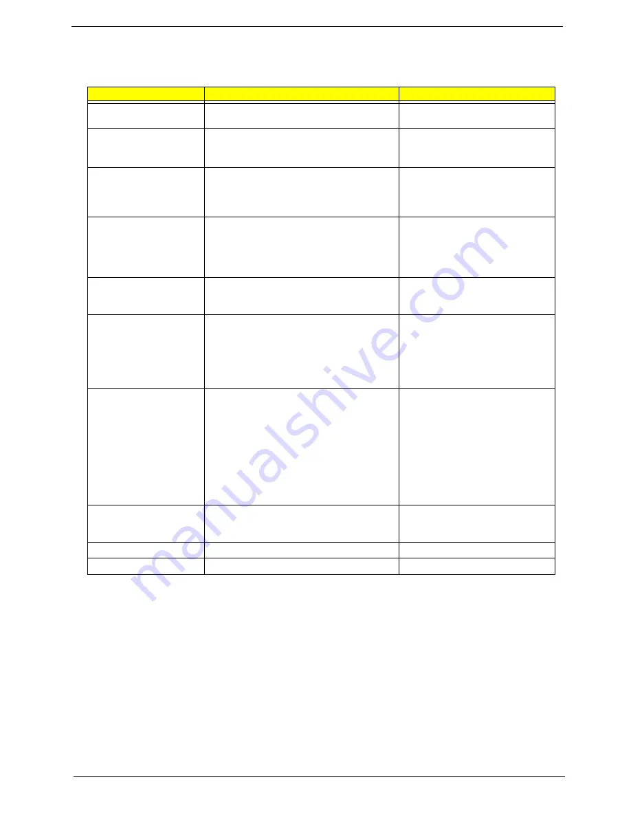
The table below describes the parameters in this screen. Settings in
boldface
are the default and suggested
parameter settings.
NOTE:
The sub-items under each device will not be shown if the device control is set to disable or auto. This is
because the user is not allowed to control the settings in these cases.
Parameter
Description
Format/Option
System Time
Sets the system time.
Format: HH:MM:SS
(hour:minute:second) System Time
System Date
Sets the system date.
Format: MM/DD/YYYY (month/day/
year)
System Date
System Memory
This field reports the memory size of the system.
The user can not change the memory setting.
This is display-only field.
Memory size is fixed to 640 KB
Extended Memory
This field reports the memory size of the
extended memory in the system. The user can
not change the memory setting. This is display-
only field.
Extended Memory size=Total memory size -1MB
VGA Memory
The total amounts of memory for VGA. The user
can not change the memory setting. This is
display-only field.
Quiet Boot
Determines if Logo will be displayed or not;
shows diagnostic screen is disabled or enabled.
Enabled: Logo is displayed, and diagnostic
screen is disabled.
Disabled: Logo is not displayed, and diagnostic
screen is enabled.
Option:
Enabled
or Disabled
Power on display
Selects display device.
Auto: During power process, the system will
detect if any display device is connected on
external video port. If any external display device
is connected, the power on display will be in CRT
(or projector) only mode. Otherwise it will be in
LCD only mode.
Both: Simultaneously enable both the integrated
LCD screen and the system’s external video port
(for an external CRT or projector).
Option:
Auto
or Both
LCD Auto Dim
Determines if the system will automatically dim
the LCD brightness in order to save power when
AC is not present.
Option:
Enabled
or Disabled
PXE Boot From LAN
Selects PXE boot from LAN function.
Option:
Enabled
or Disabled
F12 Boot Menu
Selects the F12 boot menu function.
Option:
Enabled
or
Disabled
Summary of Contents for TravelMate 370 series
Page 6: ...VI ...
Page 10: ...2 Chapter 1 System Block Diagram ...
Page 12: ...4 Chapter 1 Bottom View 1 South Bridge 3 DIMM Slot 2 DIMM Slot 4 USB port 1 2 3 4 ...
Page 50: ...42 Chapter 3 ...
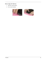
Page 51: ...Chapter 3 43 Removing the Battery 1 Slide the two battery latches 2 Then remove the battery ...
Page 76: ...68 Chapter 4 ...
Page 78: ...70 Chapter 5 Bottom View 1 South Bridge 3 DIMM Slot 2 DIMM Slot 4 USB port 1 2 3 4 ...
Page 92: ...84 Appendix B ...
Page 94: ...86 Appendix C ...
Page 95: ...www s manuals com ...


