46
Chapter 3
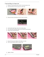
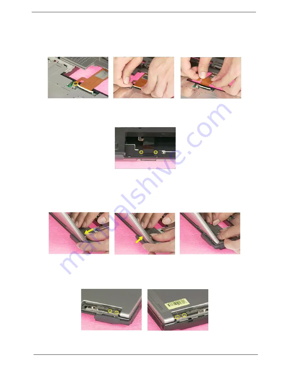
Disassembling the Main Unit
1.
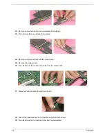
Remove one screw that secures the LCD FPC cable as the picture shows.
2.
Then disconnect the LCD FPC cable from the main board.
.
3.
Remove the two screw holding the LCD FPC cable on the bottom.
4.
Push the left and right hinge caps on the front side carefully.
5.
Then hold the left and right hinge caps on the rear side as the picture shows.
6.
Remove the left and right hinge caps.
7.
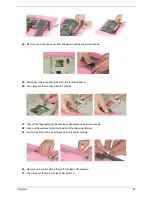
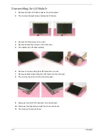
Remove the two screws holding the LCD module on one side.
8.
Then remove another two screws on the other side.
.
9.
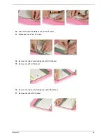
Slide the LCD latch.
Summary of Contents for TravelMate 370 series
Page 6: ...VI ...
Page 10: ...2 Chapter 1 System Block Diagram ...
Page 12: ...4 Chapter 1 Bottom View 1 South Bridge 3 DIMM Slot 2 DIMM Slot 4 USB port 1 2 3 4 ...
Page 50: ...42 Chapter 3 ...
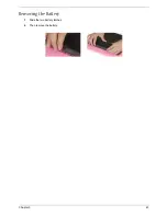
Page 51: ...Chapter 3 43 Removing the Battery 1 Slide the two battery latches 2 Then remove the battery ...
Page 76: ...68 Chapter 4 ...
Page 78: ...70 Chapter 5 Bottom View 1 South Bridge 3 DIMM Slot 2 DIMM Slot 4 USB port 1 2 3 4 ...
Page 92: ...84 Appendix B ...
Page 94: ...86 Appendix C ...
Page 95: ...www s manuals com ...

