background image

TravelMate 4650

TravelMate 4150

Service Guide

                                                                                                                                     PRINTED IN TAIWAN


Service guide files and updates are available

on the ACER/CSD web; for more information, 

please refer to 

http://csd.acer.com.tw

Summary of Contents for TravelMate 4150

Page 1: ...TravelMate 4650 TravelMate 4150 Service Guide PRINTED IN TAIWAN Service guide files and updates are available on the ACER CSD web for more information please refer to http csd acer com tw...

Page 2: ...II Revision History Please refer to the table below for the updates made on TravelMate 4650 and TravelMate 4150 service guide Date Chapter Updates...

Page 3: ...ect to the contents hereof and specifically disclaims any warranties of merchantability or fitness for any particular purpose Any Acer Incorporated software described in this manual is sold or license...

Page 4: ...bits and pieces of additional information related to the current topic WARNING Alerts you to any damage that might result from doing or not doing specific actions CAUTION Gives precautionary measures...

Page 5: ...NOT be covered in this generic service guide In such cases please contact your regional offices or the responsible personnel channel to provide you with further technical details 2 Please note WHEN OR...

Page 6: ...Touchpad Basics 23 Using a computer security lock 25 Using System Utilities 26 Acer eManagement 26 Launch Manager 27 Audio 28 Ejecting the optical CD or DVD drive tray 29 Using a Computer Security Lo...

Page 7: ...ing the HDD and ODD 65 Chapter 4 Troubleshooting 66 System Check Procedures 67 External Diskette Drive Check 67 External CD ROM Drive Check 67 Keyboard or Auxiliary Input Device Check 67 Memory Check...

Page 8: ...aceable Unit List 97 Exploded Diagram 98 Parts 100 Appendix A Model Definition and Configuration 113 Appendix B Test Compatible Components 114 Microsoft Windows XP Home Professional Environment Test 1...

Page 9: ...X Table of Contents...

Page 10: ...ravelMate 4150 series T 15 SXGA TFT LCD supporting 1400x1050 pixel resolution 16 7 million colours for TravelMate 4650 series Graphics T nVIDIA GeForceTM Go 6600 graphics processing unit GPU with 64MB...

Page 11: ...T Three analog line level stereo inputs with 5 bit volume control LINE_IN CD AUX T Two analog line level mono inputs PCBEEP PHONE IN T High quality differential CD input Storage T 40 60 80 100 GB 420...

Page 12: ...T Infrared FIR port T PC Card slot one Type II T 6 in 1 card reader SM MS MS Pro MMC SD xD Picture cardTM T DC in jack for AC adaptor T DVI D port for TravelMate 4650 series T 124 pin Acer ezDock conn...

Page 13: ...ns T 256MB 512MB 1GB DDR II 533MHz memory upgrades modules T Additional 65W AC adaptor T Additional eight cell Li ion battery pack T External USB floppy drive T Second 6 cell battery pack AcerMedia Ba...

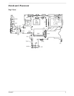
Page 14: ...Chapter 1 5 Mainboard Placement Top View...

Page 15: ...6 Chapter 1 Bottom View...

Page 16: ...P10 S VIDEO CONN JP47 RJ11 TO MDC CONN JP11 VGA B CONN JP48 RJ11 CPMM JP12 FAN CONN JP49 ODD CONN SWAP JP13 BT CONN JP50 SATA CONN JP14 KB CONN PCN1 DC JACK JP15 ROM SOCKET PCN2 MAIN BAT JP17 MIC CONN...

Page 17: ...032ARM page 11 12 13 page 17 18 19 20 AMP Audio Jack Power OK CKT page 39 page 34 Slot 0 page 24 BT Conn PATA page 15 CRT TV OUT 5in1 CardReader Slot LCD CONN page 16 page 24 page 42 49 page 28 Mini P...

Page 18: ...device which functions like a computer mouse 5 Click buttons Left center and right The left and right buttons function like the left and right mouse buttons the center button serves as a 4 way scroll...

Page 19: ...s of Bluetooth communications manufacturing option 3 Wireless communication button indicator Press to enable disable Wireless function Lights to indicate the status of wireless LAN communications 4 Po...

Page 20: ...eadphone jack Connects to audio line out devices e g speakers headphones 7 Line in mic in jack Accepts inputs from external microphones 8 Optical drive Internal optical drive accepts CDs or DVDs depen...

Page 21: ...a screw 3 PC Card slot eject button Ejects the PC Card from the slot 4 6 in 1 card reader Accepts MS MS PRO MMC SD SM and xD Picture cards NOTE Only one card can operate at any given time 5 PC Card S...

Page 22: ...external monitor LCD projector 6 S video port Connects to a television or display device with S video input 7 USB 2 0 port Connects to Universal Serial Bus USB 2 0 devices e g USB mouse USB camera 8 V...

Page 23: ...ttery to remove the battery pack 4 Battery bay Houses the computer s battery pack 5 Cooling fan Helps keep the computer cool NOTE Do not cover or obstruct the opening of the fan 6 AcerMedia Bay for Tr...

Page 24: ...ase Num lock Fn F11 When Num Lock is on the embedded keypad is in numeric mode The keys function as a calculator complete with the arithmetic operators and Use this mode when you need to do a lot of n...

Page 25: ...all windows Shift M Undoes the minimise all windows M Action R Opens the Run dialog box Application Key This key has the same effect as clicking the right mouse button it opens the application s cont...

Page 26: ...of the Sleep Button on the Power Management property Fn F5 Launch Display Mode Menu DMM Follow DMM Specification except in OS other than 32 bit Windows Fn F6 Display blank backlight off This key will...

Page 27: ...via the internal keyboard Fn F11 or the external keyboard keypad but NumLock affects the external keyboard keypad only T The NumLock shift state NumLock is off is NOT used for the cursor movement by...

Page 28: ...uld be handled by the Analog function within the keyboard controller Brightness will step up down one unit as each time these keys are pressed Fn z Brightness down Fn F10 Enter D2D recovery during POS...

Page 29: ...m right of the keyboard or hold Alt Gr and then press the Euro symbol at the upper center of the keyboard The US dollar sign 1 Open a text editor or word processor 2 Either directly press the dollar s...

Page 30: ...ed Num Lock Lights when Num Lock is activated Media activity Lights when the hard disk or optical drive is active Bluetooth indicator Lights to indicate the status of Bluetooth communications Wireless...

Page 31: ...users To set the Web browser mail and programmable keys run the Acer Launch Manager Launch Key Default Application Acer eManager user programmable P User programmable Web browser Internet browser user...

Page 32: ...e the touchpad T Move your finger across the touchpad 2 to move the cursor T Press the left 1 and right 4 buttons located on the edge of the touchpad to perform selection and execution functions These...

Page 33: ...ease the touchpad s responsiveness Function Left button 1 Right button 4 Main touchpad 2 Center button 3 Execute Click twice quickly Tap twice at the same peed as double clicking a mouse button Select...

Page 34: ...the computer lets you connect a Kensington compatible computer security lock Wrap a computer security lock cable around an immovable object such as a table or handle of a locked drawer Insert the loc...

Page 35: ...resolution settings when connecting to a projector Acer eRecovery Creates backups and recovers system configurations reliably Acer eSettings Makes managing system settings and security easy Function D...

Page 36: ...r allows you to set the four launch keys located above the keyboard You can access the Launch Manager by clicking on Start All Programs and then Launch Manager to start the application Launch keys on...

Page 37: ...1 Audio The computer comes with 16 bit high fidelity AC 97 stereo audio and dual stereo speakers Adjusting the Volume Adjusting the volume on the computer is as easy as pressing some buttons Hot keys...

Page 38: ...ecting the optical CD or DVD drive tray To eject the optical drive tray when the computer is turned on press the drive eject button When the power is off you can eject the drive tray using the mechani...

Page 39: ...de of the computer lets you connect a Kensington compatible computer security lock Wrap a computer security lock cable around an immovable object such as a table or handle of a locked drawer Insert th...

Page 40: ...iated shutdown All devices in the system are turned off completely On Working G0 S0 Individual devices such as the CPU and hard disk may be power managed in this state S3 Sleeping State CPU set power...

Page 41: ...M ICH6 M Intel 915GM ICH6 M Super I O controller SMsC LPC47N217 Audio controller ICH6 M Video controller Integrated VGA solution for 915GM External VGA card for 915PM Hard disk drive controller ICH6 M...

Page 42: ...eed 533MHz Supports Dimm Voltage 1 8V Supports Dimm Package 200 pin Supports 64MB 128MB for NV43M NV44MV Adjustable 128MB UMA VGA share from North Bridge ICH 6M Memory Module Combinations You can inst...

Page 43: ...level 2 0 OHCI USB 2 0 Number of USB port 4 Location Left Side 3 Rear Side 1 Item Specification Audio Controller AC 97 Codec Audio onboard or optional Built in Mono or Stereo Stereo Resolution 20 bit...

Page 44: ...ternational language support Four easy launch buttons T Internet browser T email with LED T Empowering key T one user programmable button Two front access LED buttons T WLAN LED button T Bluetooth LED...

Page 45: ...0 279 Number of Colors 262K 262K 262K Color Saturation NTSC 45 45 45 View Angle H V 80 40 80 40 20 40 45 45 Brightness cd m2 5 points average 180 200 160 Contrast Ratio 300 1 300 1 250 1 Response Time...

Page 46: ...at 100 240Vac AC input full load warm up condition Output Ratings CV mode DC output voltage Offers constant voltage 19 0V output source with 150W max output power capacity Noise Ripple 300mvp pmax 20M...

Page 47: ...wer Down Hard Disk Power Down Super I O Power Down Sleeping State S4 Also called Hibernate state System saves all system states and data onto the disk prior to power off the whole system Dimensions an...

Page 48: ...K6025GAS 60GB MK8025GAS 8MB 80GB Nominal Power Requirements Logic 5V 5V 5V Start 4 7watts 5 0watts 4 7watts Seeking 2 6watts 2 9watts 2 6watts Reading Writing 2 3watts 2 5watts 2 3watts Idle 0 9watts...

Page 49: ...9 8 M S2 1 0G 5 500 Hz Operating Shock 200g 200g 200g Non Operating Shock 800g 800g 800g Reliability Characteristics Error Rates Non recoverable 1 in 1013 bits 1 in 1013 bits 1 in 1013 bits Seek 1 in...

Page 50: ...rage ms 7 1 7 1 7 1 5 5 Media transfer rate Mbits sec max 350 350 350 493 Interface transfer rate MB sec max 100MB sec Ultra DMA mode 5 100MB sec Ultra DMA mode 5 100MB sec Ultra DMA mode 5 100 Ultra...

Page 51: ...ms 200G 2ms 200G 2ms 300 G 2ms 160G 1ms Vibration random RMS 0 67 G 5 500 Hz 0 67 G 5 500 Hz 0 67 G 5 500 Hz NA Swept sine 1 G 0 P 5 500 Hz 1 G 0 P 5 500 Hz 1 G 0 P 5 500 Hz NA Non operating Ambient t...

Page 52: ...en Press F2 to enter Setup message is prompted on the bottom of screen The setup screen displays BIOS as follows Navigating the BIOS Utility During setup all Fn function keys and power saving function...

Page 53: ...erating system If press power button for less than 4 seconds the system will enter suspend to RAM or OFF state according to OS power option setting Lid Switch This section describes the expected behav...

Page 54: ...lid Passwrod T If the password is correct system will continue to boot up into OS T Password on boot T Password on boot is Disabled the system will NOT POP any password prompt windows during POST T If...

Page 55: ...ou Serial Number This item will show the Serial number of system Asset Tag This item will show the Asset Tag number of the system UUID This will be visible only when there is an internal LAN device pr...

Page 56: ...e TurboCache 32MB actual TurboCache VRAM size Intel 915 DVMT selectable between the following 1 64MB 8MB pre allocated 56MB DVMT 2 128MB 8MB pre allocated 128DVMT This is the default value 3 Max DVMT...

Page 57: ...e is enabled When this is not selected Boot from LAN feature is then disabled F12 Boot Menu When this is selected users can modify device boot priority by pressing F12 key during POST When this is not...

Page 58: ...Support Disabled Normal 16550 COM1 3F8 IRQ4 IrDA HPSIR COM2 2F8 IRQ3 ASK IR COM3 3E8 IRQ4 FAST IR COM4 2E8 IRQ3 DMA Setting For FIR DMA1 DMA2 DMA3 OK Cancel Tab Right Left for block select Up Down for...

Page 59: ...red port Disabled COM1 3F8 IRQ4 COM2 2F8 IRQ3 COM3 3E8 IRQ4 COM4 2E8 IRQ3 DMA Setting for Fast IR Sets a DMA channel for the printer to operate in ECP mode This parameter is enabled only if Mode is se...

Page 60: ...happened The following sub options are all requires the Supervisor password for changes and should be grayed out if the user password was used to enter setup When you set Supervisor password already...

Page 61: ...rd Drive 2 CD ROM DVD Drive 3 Floppy Drive 4 Network Boot since only 3 items are availble if above 3 items are invalid a boot menu should be shown when boot Insyde Software SCU May 20 2003 5 40 09 Mai...

Page 62: ...reboot Tab Right Left for block select Up Down for item select Enter for accept Cancel Esc for reject Alt activates accelerators Space for Enable or Disable OK Cancel Insyde Software SCU May 20 2003...

Page 63: ...item select Enter for accept Cancel Esc for reject Alt activates accelerators Space for Enable or Disable Insyde Software SCU May 20 2003 5 40 09 Main Advanced Security Boot Exit Exit Saving Changes...

Page 64: ...preventing electrostatic discharge T Small Philips screw driver T Philips screwdriver T Plastic flat head screw driver T Tweezers NOTE The screws for the different components vary in size During the...

Page 65: ...d all peripherals 2 Unplug the AC adapter and all power and signal cables from the system 3 Remove the battery pack NOTE The screws used to secure bottom case and upper case are more than one type Ple...

Page 66: ...Chapter 3 57 Removing the Battery Pack 1 Unlock the battery lock 2 Slide the battery latch as shown then remove the battery pack...

Page 67: ...one screw that secure the RAM door and remove it away 2 Pop up the memory then remove it Removing the Keyboard 1 Pull the strip cover 2 Remove the two screws to release the keyboard Pull the keyboard...

Page 68: ...to detach the LED Panel 5 Detach the LED panel out from the system Removing the Thermal and Bluetooth Module 1 Remove the two screws to detach the thermal door 2 Disconnect the bluetooth cable from th...

Page 69: ...the mainboard 5 Detach the upper case to the system 6 Pull the upper cared forward 7 Release both side tabs to disconnect the touchpad board cable from the mainboard Removing the Touchpad 1 Disconnec...

Page 70: ...ouchpad cable from the trace board 7 Detach the trace board from here Removing the FAN 1 Disconnect the system fan cable 2 Remove the two screws to release the system fan from here 3 Detach the system...

Page 71: ...ection with a flat screw driver to loosen the CPU 7 Detach the CPU out from the system Removing the MDC 1 Disconnect the MDC cable from the mainboard 2 Remove the two screws to loosen the DMC board 3...

Page 72: ...wn the button to release the PCMCI dummy card then pull the dummy card out from the system 4 Remove the one screw to loosen the mainobard 5 Push outward of the side before releasing the mainboard out...

Page 73: ...on each side to detach the LCD panel from the case 8 Lift up the panel then take it out from the case 9 Remove the one screw on each side to detach the antenna from the case 10 Gently to tear the tabs...

Page 74: ...two screws on each side 2 Detach the HDD bracket from the HDD unit 3 Remove the two screws located on both side to detach the ODD unit from bracket 4 Push backward to release the ODD bracket from the...

Page 75: ...r products Non Acer products prototype cards or modified options can give false errors and invalid system responses 1 Obtain the failing symptoms in as much detail as possible 2 Verify the symptoms by...

Page 76: ...he drive to fail Do the following to select the test device 1 Boot from the diagnostics diskette and start the diagnostics program 2 See if CD ROM Test is passed when the program runs to CD ROM Test 3...

Page 77: ...MM is fully installed into the connector A loose connection can cause an error Power System Check To verify the symptom of the problem power on the computer using each of the following power sources 1...

Page 78: ...following T Replace the System board T If the problem is not corrected see Undetermined Problems on page 80 T If the voltage is not correct go to the next step NOTE An audible noise from the power ad...

Page 79: ...attery pack that has less than 50 of the total power remaining when installed in the computer If the battery status indicator does not light up remove the battery pack and let it return to room temper...

Page 80: ...xt possible FRU to be replaced when servicing a computer If the symptom is not listed see Undetermined Problems on page 80 The following lists the error messages that the BIOS displays on the screen a...

Page 81: ...ult Settings in BIOS Setup Utility Hard disk drive System board Stuck Key see Keyboard or Auxiliary Input Device Check on page 67 Keyboard error see Keyboard or Auxiliary Input Device Check on page 67...

Page 82: ...Setup Utility System cache error Cache disabled System board CPU ID System board DMA Test Failed DIMM System board Software NMI Failed DIMM System board Fail Safe Timer NMI Failed DIMM System board De...

Page 83: ...ource battery pack and power adapter See Power System Check on page 68 Reconnect the LCD connector Hard disk drive LCD inverter ID LCD cable LCD Inverter LCD System board No beep power on indicator tu...

Page 84: ...E7h Go to BIOS E8h Set Huge Segment E9h Initialize Multi Processor EAh Initialize OEM special code EBh Initialize PIC and DMA ECh Initialize Memory type EDh Initialize Memory size EEh Shadow Boot Blo...

Page 85: ...able LCD System board Indicator Related Symptoms Symptom Error Action in Sequence Indicator incorrectly remains off or on but system runs correctly Reconnect the inverter board Inverter board System b...

Page 86: ...hibernation Keyboard if control is from the keyboard Hard disk drive System board The system doesn t enter hibernation mode and four short beeps every minute See Hibernation Mode on page 34 Press Fn...

Page 87: ...Ensure the Parallel Port in the Onboard Devices Configuration of BIOS Setup Utility is set to Enabled Onboard Devices Configuration Run printer self test Printer driver Printer cable Printer System Bo...

Page 88: ...discharge or software errors FRU replacement should be considered only when a recurring problem exists When analyzing an intermittent problem do the following 1 Run the advanced diagnostic test for th...

Page 89: ...perating correctly See Power System Check on page 68 1 Power off the computer 2 Visually check them for damage If any problems are found replace the FRU 3 Remove or disconnect all of the following dev...

Page 90: ...Recovery 1 Prepare NAPP CD Recovery CD and System CD 2 Put NAPP CD into the optical drive Then boot up the system 3 The system will ask you if you want to build NAPP Master HDD Please press any key to...

Page 91: ...e This step is to create image files to the system you do not have to put the Recovery CD to the optical drive in order Place one Recovery CD to the drive at one time till you finish all Recovery CDs...

Page 92: ...83 Chapter 4 7 Then insert the System CD to the optical drive 8 You will see the screen displaying PASS when the system has buit NAPP Master hard disc drive...

Page 93: ...PP CD Recovery CD and System CD 2 Put NAPP CD into the optical drive Then boot up the system 3 The system will ask you if you want to build NAPP Master HDD Please press any key to continue 4 NAPP CD w...

Page 94: ...nguages Recovery not more than five languages could be loaded to the system 6 Put the Recovery CD to the optical drive This step is to create image files to the system you do not have to put the Recov...

Page 95: ...Chapter 4 86 After you place the Recovery CD to the optical drive you will see the display below 7 Then insert the System CD to the optical drive...

Page 96: ...87 Chapter 4 8 You will see the screen displaying PASS when the system has buit NAPP Master hard disc drive...

Page 97: ...Chapter 5 88 Top View Jumper and Connector Locations Chapter 5...

Page 98: ...89 Chapter 5 Rear View...

Page 99: ...P10 S VIDEO CONN JP47 RJ11 TO MDC CONN JP11 VGA B CONN JP48 RJ11 CPMM JP12 FAN CONN JP49 ODD CONN SWAP JP13 BT CONN JP50 SATA CONN JP14 KB CONN PCN1 DC JACK JP15 ROM SOCKET PCN2 MAIN BAT JP17 MIC CONN...

Page 100: ...91 Chapter 5 VGA Board Item Description JP1 VGA Board to MB connector JP2 LCD Connector...

Page 101: ...Chapter 5 92 Power SW B Item Description JP1 Power Board to MB Connector SW1 Power Switch SW2 e Manager SW3 Launch Manager Switch SW4 Internet Switch SW5 E mail Switch...

Page 102: ...hapter 5 TouchPad Board Item Description JP1 Trace Pad Board Connector SW1 B T Switch SW2 Wireless Switch SW3 Left Bottom SW4 Right Bottom SW5 Scroll Up SW6 Scroll Left SW7 Scroll Bottom SW8 Scroll Ri...

Page 103: ...Chapter 5 94 Hot Swap ODD Board Item Description JP1 Hot Swap JP2 ODD device Connector...

Page 104: ...95 Chapter 5 DVI Board Item Description JP1 DVI Board Connector...

Page 105: ...Chapter 5 96 Clear CMOS...

Page 106: ...change is made it will not be noted on the printed Service Guide For ACER AUTHORIZED SERVICE PROVIDERS your Acer office may have a DIFFERENT part number code from those given in the FRU list of this p...

Page 107: ...98 Chapter 6 Exploded Diagram...

Page 108: ...Chapter 6 99...

Page 109: ...LS PANASONIC CGR18650CE BATTERY LI ION 8 CELLS PANASONIC CGR18650CE BT 00805 001 BATTERY LI ION 8 CELLS SONY US18650G5 BATTERY LI ION 8 CELLS SONY US18650G5 BT 00804 004 BOARD MODEM BOARD ZL1A MODEM B...

Page 110: ...55 T75V5 004 LCD INVERTER LCD INVERTER 19 T75V5 001 CABLE FFC CABLE T P TO T P BOARD FFC CABLE T P TO T P BOARD 50 T75V5 001 BLUETOOTH CABLE BLUETOOTH CABLE 50 T75V5 002 POWER CORD US 3 PIN POWER COR...

Page 111: ...CABLE 15 IN XGA 50 T75V5 005 LCD WIRE CABLE 15 IN SXGA LCD WIRE CABLE 15 IN SXGA 50 T75V5 006 CASE COVER BRACKET ASSEMBLY MIDDLE COVER W BUTTON MIDDLE COVER W BUTTON 42 T75V5 001 UPPER CASE W FRONT C...

Page 112: ...LOGO W ANTENNA LCD PANEL WITH LOGO W ANTENNA 60 T75V5 004 LCD BEZEL 14 IN LCD BEZEL 14 IN 60 T75V5 005 LCD BEZEL 15 IN LCD BEZEL 15 IN 60 T75V5 006 LCD BRACKET W HINGE 14 IN SET LCD BRACKET W HINGE 1...

Page 113: ...ESSOR INTEL PENTIUM M 1 6G 2M 533FSB uFCPGA2 SL86G C 1 STEPPING INTEL DOTHAN 730 1 6GHZ 2M FSB5330 KC N0001 730 INTEL PENTIUM M 1 73G 2M 533FSB uFCPGA2 SL7SA C 1 STEPPING INTEL DOTHAN 740 1 73GHZ 2M F...

Page 114: ...243N 6M T75V5 002 DVD CDRW COMBO 24X DRIVE HLDS GCC 4243N G BASE DVD CDRW COMBO 24X DRIVE HLDS GCC 4243N G BASE KO 02405 005 DVD DUAL MODULE PIONEER DVR K15RA SWAP DVD DUAL MODULE PIONEER DVR K15RA 6M...

Page 115: ...5 006 OPTICAL DEVICE BOARD OPTICAL DEVICE BOARD 55 T75V5 005 HDD CARRIER HDD CARRIER 60 T75V5 003 HDD HARD DISK DRIVE HDD SEAGATE 40G 4200rpm ST94019A 2MB F W 3 05 HDD SEAGATE 40G 4200rpm ST94019A 2MB...

Page 116: ...LUTO MK1031GAS F W AA20 HDD 100GB 2 5IN 4200RPM TOSHIBA PLUTO MK1031GAS F W AA20 KH 10004 001 HDD 100GB 2 5IN 4200RPM SEAGATE N2 ST9100822A F W 3 01 HDD 100GB 2 5IN 4200RPM SEAGATE N2 ST9100822A F W 3...

Page 117: ...NGARIAN KEYBOARD DARFON HUNGARIAN KB T5902 013 KEYBOARD DARFON SPANISH KEYBOARD DARFON SPANISH KB T5902 010 KEYBOARD DARFON LA KEYBOARD DARFON LA TBD KEYBOARD DARFON ICE LAND KEYBOARD DARFON ICE LAND...

Page 118: ...03 LCD 14 IN XGA TOPPOLY TD141TGCD2 LCD 14 IN XGA TOPPOLY TD141TGCD2 LK 14101 003 LCD 15 IN XGA LG LP150X08 A3 LCD 15 IN XGA LG LP150X08 A3 LK 15008 016 LCD 15 IN XGA CMO N150X3 L07 LCD 15 IN XGA CMO...

Page 119: ...CD5 KN 2560B 011 MEMORY MICRON 512MB 533MHZ MT8HTF6464HDY 53EA2 MEMORY MICRON 512MB 533MHZ MT8HTF6464HDY 53EA2 KN 51204 015 MEMORY IFX 512MB 533MHZ HYS64T64020HDL 3 7 A MEMORY IFX 512MB 533MHZ HYS64T...

Page 120: ...V7 001 HEATSINK THERMAL MODULE ZL2 CPU HEATSINK ASSY 60 T63V7 003 POINTING DEVICE TOUCHPAD TOUCHPAD 54 T75V5 001 SPEAKER SPEAKER SET R L 2W SPEAKER SET R L 2W 23 T75V5 003 MISCELLANEOUS NAME PALTE TM4...

Page 121: ...4 SCREW M2 5 10 NL SCREW M2 5 10 NL 86 T75V5 005 SCREW M2 5 18 NL SCREW M2 5 18 NL 86 T75V5 006 SCREW M2 3 NL SCREW M2 3 NL 86 T75V5 007 SCREW M2 0 3 Ni NL HEAD SIZE 3 0 SCREW M2 0 3 Ni NL HEAD SIZE 3...

Page 122: ...hip Memory1 Memory2 HDD Optical Card Reader Wireless LAN Blue tooth Battery Ada pter TM4152LMi PM 740 N15 XGA UMA SO256MB II5 SO256MB II5 N60GB 4 2K NDU8X 6 in 1 INT2200B G_MW NA 8CELL 2 2 65W TM4152L...

Page 123: ...dows XP Home environment Refer to the following lists for components adapter cards and peripherals which have passed these tests Regarding configuration combination and test procedures please refer to...

Page 124: ...TOSHIBA 2 5 40G4200 MK4025GAS KA100A Pluto RohS 2 5 60G4200 MK6025GAS Pluto RohS 2 5 80G4200 MK8025GAS 8MB Pluto RohS 2 5 100G4200 MK1031GAS RohS CTU Jan 2 5 60G5400 MK6026GAX 16MB Proteus RohS Seaga...

Page 125: ...l 4S2P 4400mAh LI 1 9MAH 6C 2nd battery follows Kingfisher s Spec Sanyo 6cell 3S2P 3800mAh 1 9AHr Prismatic Panasonic LI 2 2MAH 8C Panasonic Li ion Normal 8cell 4S2P 4500mAh ADAPTER Liteon Adapter 65W...

Page 126: ...117 Appendix B...

Page 127: ...of Acer s Notebook Desktop and Server models including T Service guides for all models T User s manuals T Training materials T Bios updates T Software utilities T Spare parts lists T TABs Technical A...

Reviews: