Chapter 3
45
External Module Disassembly Process
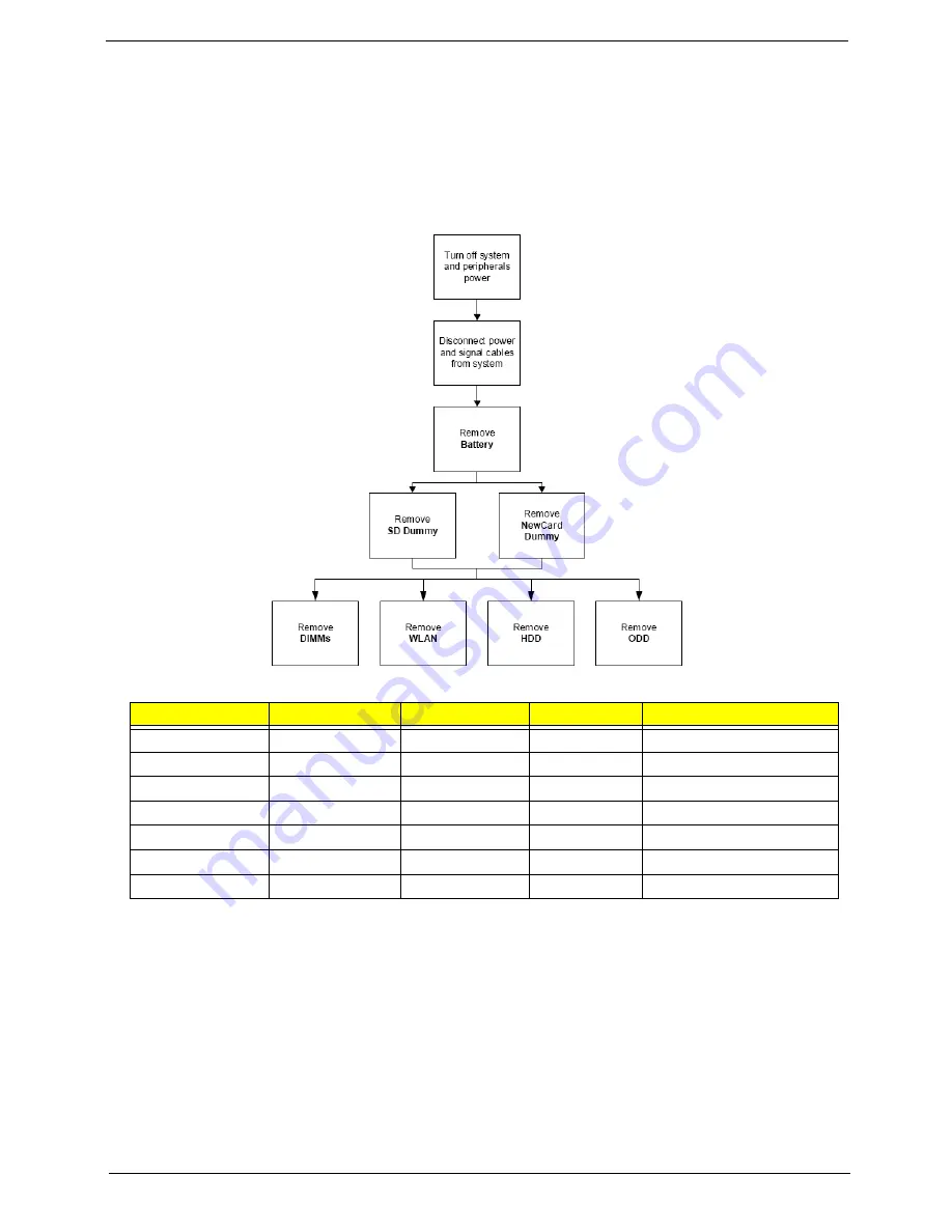
External Modules Disassembly Flowchart
The flowchart below gives you a graphic representation on the entire disassembly sequence and instructs you
on the components that need to be removed during servicing. For example, if you want to remove the main
board, you must first remove the keyboard, then disassemble the inside assembly frame in that order.
Screw List
Step
Screw
Quantity
Color
Part No.
Memory Cover
M2.5*8 (NL)
4
Black
MA000005YG0
HDD Cover
M2*6 (NL)
2
Black
MMCK20060G0
WLAN Cover
M2.5*8 (NL)
4
Black
MA000005YG0
WLAN Module
M2*3 (NL)
2
Black
MA0000060G0
HDD Carrier
M3*3 (NL)
4
Silver
MAAA03032G0
ODD Module
M2.5*5(NL)
1
Black
MA000002NG0
ODD Bracket
M2*3 (NL)
3
Black
MA0000060G0
Summary of Contents for TravelMate 4730 Series
Page 6: ...VI ...
Page 10: ...X Table of Contents ...
Page 14: ...4 Chapter 1 System Block Diagram ...
Page 34: ...24 Chapter 1 ...
Page 52: ...42 Chapter 2 ...
Page 60: ...50 Chapter 3 7 Remove the WLAN cover as shown ...
Page 95: ...Chapter 3 85 7 Lift the Thermal Module clear of the Mainboard ...
Page 114: ...104 Chapter 3 3 Connect the RJ 11 cable to the modem module as shown ...
Page 118: ...108 Chapter 3 2 Replace the two securing screws ...
Page 122: ...112 Chapter 3 2 Connect the seven cables on the mainboard as shown B C D E F G A ...
Page 128: ...118 Chapter 3 3 Turn the computer over and replace the five securing screws ...
Page 175: ...Chapter 6 165 ...
Page 184: ...Appendix A 174 ...
Page 188: ...178 Appendix B ...
Page 190: ...180 Appendix C ...
Page 193: ...183 Wireless Function Failure 136 WLAN Board 52 ...
Page 194: ...184 ...


