54
Chapter 3
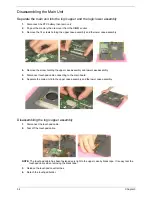
Disassembling the Main Unit
Separate the main unit into the logic upper and the logic lower assembly
1.
Disconnect the RTC battery then remove it.
2.
Pop out the memory then remove it from the DIMM socket.
3.
Remove the 14 screws holding the upper case assembly and the lower case assembly.
4.
Remove the screw holding the upper case assembly and lower case assembly.
5.
Disconnect touchpad cable connecting to the main board.
6.
Separate the main unit into the upper case assembly and the lower case assembly.
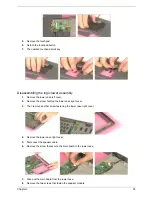
Disassembling the logic upper assembly
1.
Disconnect the touchpad cable.
2.
Tear off the touchpad cable.
NOTE:
The touchpad cable has been fastened very tight to the upper case by black tape. It is easy tear the
touchpad cable when removing the black tape.
3.
Release the touchpad cover latches.
4.
Detach the touchpad holder.
Summary of Contents for TravelMate C300 Series
Page 6: ...VI ...
Page 8: ...VIII Table of Contents ...
Page 21: ...Chapter 1 13 Num loc Lights when Num Lock is activated Icon Function Description ...
Page 42: ...34 Chapter 1 ...
Page 67: ...Chapter 3 59 ...
Page 88: ...80 Chapter 4 ...
Page 101: ...Chapter 6 93 ...
Page 110: ...102 Appendix B ...
Page 112: ...104 Appendix C ...
Page 115: ...Index 107 ...

