10
Chapter 1
3
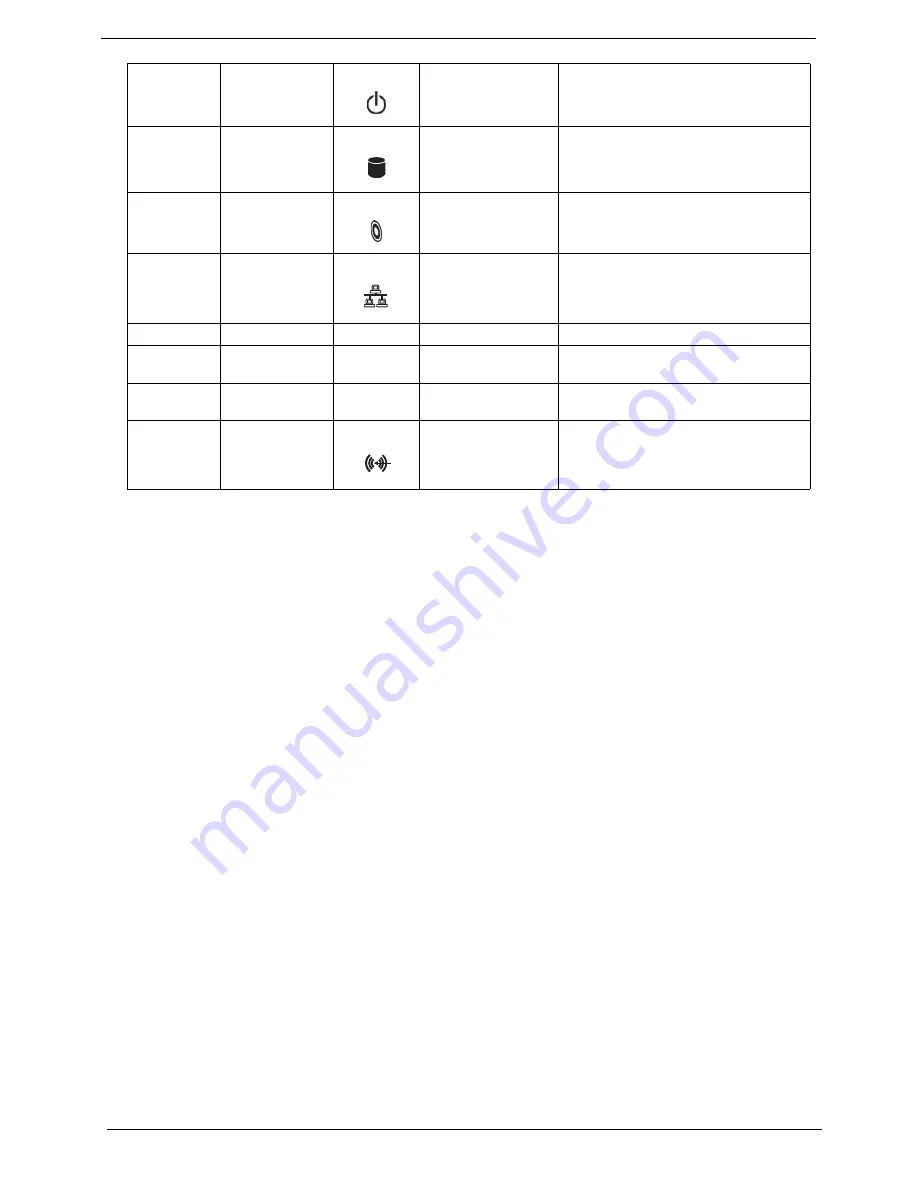
Power button
Power on or off the system.
4
Hard disk drive
indicator
Lights to indicate hard disk drive status.
5
Optical disk drive
indicator
Lights to Indicate optical disk drive status.
6
LAN indicator
Press to enable/disable Wireless function.
Lights to indicate the status of wireless
LAN communications.
7
USB ports
8
Microophone-in jack
(front)
9
Headphone/Speaker-
out/line-out port
10/11
Line-in jack
Accepts audio line-in devices (e.g., audio
CD player, stereo walkman).
Note:
"Connecting peripherals" on page 14
"Connecting
options" on page 19
Icon
Component
Icon
Component
Note:
"Connecting peripherals" on page 14
"Connecting
options" on page 19
Icon
Component
Icon
Component
Summary of Contents for Veriton 7900Pro
Page 17: ...Chapter 1 11 Rear panel Veriton 5900Pro rear view Veriton 6900Pro rear view ...
Page 24: ...18 Chapter 1 ...
Page 34: ...28 Chapter 1 ...
Page 42: ...36 Chapter 2 Total Memory Base Upper Extended Total Memory N A Parameter Description Options ...
Page 73: ...Chapter 3 67 2 Detach the USB board with its upper bracket then pull out the USB audio cables ...
Page 79: ...Chapter 3 73 2 Detach the ODD module from the chassis 3 Detach the card reader carefully ...
Page 82: ...76 Chapter 3 4 Then remove the power supply from the chassis ...
Page 90: ...84 Chapter 3 3 Remove the four screws holding the system fan 4 Detach the system fan ...
Page 92: ...86 Chapter 3 4 Remove the screw fastening the LED module then detach the LED module ...
Page 108: ...102 Chapter 4 ...
Page 112: ...106 Chapter 6 Veriton 7900Pro Exploded Diagram ...
Page 113: ...Chapter 6 107 Veriton 6900Pro Exploded Diagram ...
Page 116: ...110 Chapter 6 ...


